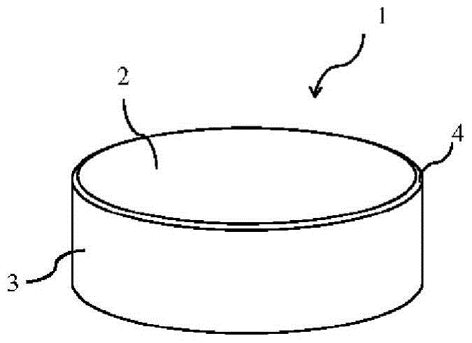
cutting tool

A cutting tool and cutting edge technology, used in the manufacture of tools, workpieces, turning equipment, etc., can solve problems such as tool performance optimization, and achieve the effect of extending tool life

Active Publication Date: 2017-03-08
KYOCERA CORP
View PDF7 Cites 0 Cited by
  • Summary
  • Abstract
  • Description
  • Claims
  • Application Information

AI Technical Summary

Problems solved by technology

[0012] However, like the silicon nitride-based sintered bodies described in Patent Documents 1 and 2, the method of controlling the residual stress of the entire sintered body cannot be said to have optimized tool performance when used as a cutting tool.

Method used


Image

  • cutting tool
  • cutting tool
  • cutting tool

Examples


Embodiment 1

[0050] As a raw material, according to the ratio in Table 1, silicon nitride (Si 3 N 4 ) powder, RE element oxide powder with an average particle size of 1.2 μm, alumina (Al oxide with an average particle size of 0.7 μm) 2 O 3 ) powder, aluminum nitride (AlN) powder with an average particle size of 0.7 μm, and titanium nitride (TiN) powder with an average particle size of 2.5 μm, after adding a binder and a solvent, they were pulverized by a stirring ball mill and mixed for 72 hours.

[0051] After that, drying was performed to remove the solvent, and granulated powder was produced, and the granulated powder was filled into a die for extrusion molding in the shape of a cutting tool of SNMG1204 shape and RNGN1204 shape. Then, while adjusting the moving speed of the upper and lower punches and the time for applying the load, extrusion molding was performed by applying a molding load of 3000 kg. The green density was measured for 10 shaped bodies in the shape of SNMG1204. For...

Embodiment 2

[0071] As a raw material, silicon nitride (Si 3 N 4 ) powder, alumina with an average particle size of 0.7 μm (Al 2 O 3 ) powder, aluminum nitride (AlN) powder with an average particle size of 1.5 μm, yttrium oxide (Y) with an average particle size of 1.0 μm 2 O 3 ), silicon oxide (SiO) with an average particle size of 1.0 μm 2 ), titanium nitride (TiN) powder with an average particle diameter of 1.0 μm, after adding a binder and a solvent, it was pulverized by a stirring ball mill and mixed for 72 hours.

[0072] Then, the solvent was removed by drying, and granulated powder was produced, and the granulated powder was filled into a die for extrusion molding in the shape of a cutting tool of RNGN120412 shape. Then, extrusion molding was performed by applying a molding load of 3000 kg while adjusting the moving speed of the upper and lower punches and the time for applying the load. The green density ratio of Example 1 was set to 1.035. After that, Mn paste coating was c...


PUM

PropertyMeasurementUnit
tensile stressaaaaaaaaaa
particle sizeaaaaaaaaaa

Abstract

The present invention provides a cutting tool made of a silicon nitride-based sintered body with high fracture resistance, in which the residual stress on the rake face and the flank face is in an appropriate range. A cutting tool (1) is composed of a silicon nitride-based sintered body containing a silicon nitride-based phase at a ratio of 50% by volume or more and a titanium nitride-based phase at a ratio of 10 to 30% by volume. The intersecting ridge portion of the rake face (3) is used as the cutting edge (4), the residual stress received by the titanium nitride phase is tensile stress, and the tensile stress received by the titanium nitride phase of the rake face (2) is greater than Tensile stress on the titanium nitride phase of the flank (3).

Description

technical field [0001] The present invention relates to a cutting tool composed of a silicon nitride-based sintered body. Background technique [0002] The silicon nitride-based sintered body mainly composed of silicon nitride and sialon (sialon) can be used in harsh environments because of its light weight and excellent wear resistance, strength and high temperature strength. used under cutting conditions. Therefore, it is suitable for high-speed rough cutting and the like. [0003] Among the cutting tools made of such a silicon nitride-based sintered body, for example, Patent Document 1 discloses a silicon nitride-based sintered body having an absolute value of residual stress of 42 to 55 MPa, and it is described that by making the residual stress The absolute value of is below 45MPa, which can achieve high strength at room temperature and high temperature. [0004] In addition, Patent Document 2 discloses that, after grinding the surface of a silicon nitride-based sint...

Claims


Application Information

Patent Timeline
Patent Type & Authority Patents(China)
IPC IPC(8): B23B27/14
CPCC04B35/5935C04B2235/3225C04B2235/3222C04B2235/3418C04B2235/3267C04B2235/3886C04B2235/3895C04B2235/3869C04B2235/3873C04B2235/3865C04B2235/3232C04B2235/6565C04B2235/5445C04B2235/5436C04B2235/76C04B2235/77B23B27/14B23B2224/36B23B2222/36C04B2235/3217C04B2235/6562C04B2235/6567Y10T407/24B23B27/148B23B2228/10B23B2228/24C04B35/584
Inventor 山本晋辅
Owner KYOCERA CORP
Why Eureka
Try Eureka