A high voltage linear constant current led drive circuit

A technology of LED drive and constant current control circuit, which is applied in the direction of lamp circuit layout, electric light source, lighting device, etc., can solve the problems of low power factor, increased production cost, poor linear adjustment rate, etc., and achieve simple and reasonable circuit structure, improve The effect of service life and reducing the cost of the whole lamp

Active Publication Date: 2017-11-17
FOSHAN TOPDAY OPTOELECTRONICS TECH
View PDF6 Cites 0 Cited by
  • Summary
  • Abstract
  • Description
  • Claims
  • Application Information

AI Technical Summary

Problems solved by technology

Existing LED drive circuits can be divided into two types: switch-type and linear constant-current LED drive circuits. However, the structure of switch-type drive circuits is complex, so the market is beginning to use linear constant-current drive circuits that are more conducive to mass production.
[0004] The linear constant current drive circuit has the advantages of simple circuit, easy mass production and high efficiency, but it still has some shortcomings. For example, most of the existing linear constant current drive circuits are realized by high-voltage linear constant current IC chips. IC chips are relatively expensive, and their production costs increase accordingly. At the same time, the existing linear constant current drive circuits generally have poor linear adjustment rate, low power factor, and generally cannot achieve dimming, which cannot meet the requirements of LED drive. Due to the high performance and multi-function requirements of the circuit, it is necessary to develop a linear constant current LED drive circuit with low cost, good performance and dimming function.

Method used


Image

  • A high voltage linear constant current led drive circuit
  • A high voltage linear constant current led drive circuit
  • A high voltage linear constant current led drive circuit

Examples


Embodiment 1

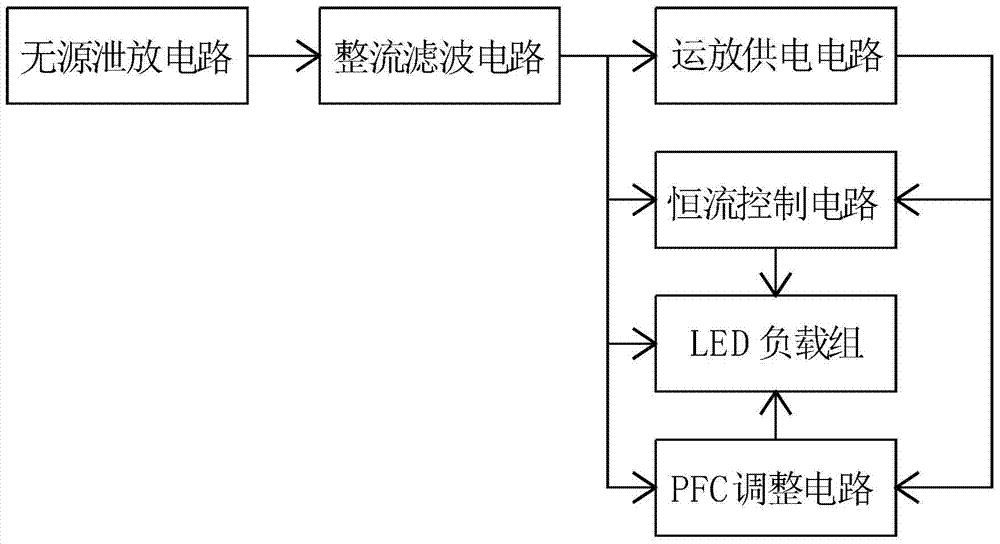
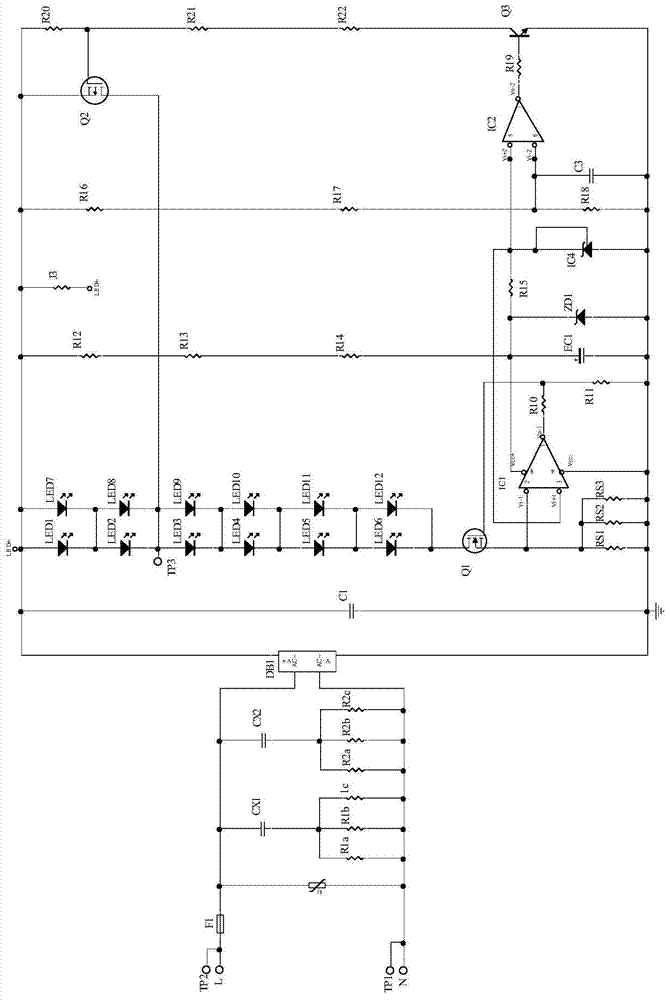
[0027] Such as figure 2 As shown, in this embodiment, the operational amplifier power supply circuit includes resistors R12, R13, R14 and capacitor EC1 connected in series, the resistor R12 is connected to the voltage bus output by the rectification and filtering circuit, and the resistor R14 is connected to the capacitor EC1 grounded. The PFC adjustment circuit includes an operational amplifier IC2, a voltage reference IC4, a first sampling resistor, switch tubes Q3 and Q2, the switch tube Q3 is a triode, the switch tube Q2 is a P-type MOS tube, the resistor R14 is connected to the The connection point of the capacitor EC1 is connected to the operational amplifier IC2 through a resistor R15 and supplies power to it; the anode of the voltage reference IC4 is grounded, and the cathode is connected to the positive phase input terminal of the operational amplifier IC2, which is the positive phase of the operational amplifier IC2 The input terminal provides a fixed voltage refer...

Embodiment 2

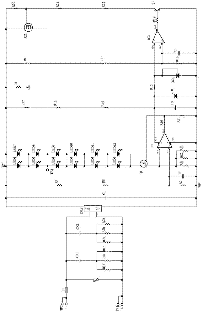
[0034] Such as figure 1 and image 3 As shown, the difference between this embodiment and Embodiment 1 is that the constant current control circuit includes a second sampling resistor, a sampling resistor RS, a switch tube Q1 and an operational amplifier IC1. The connection point of the resistor R14 in the power supply circuit of the operational amplifier and the capacitor EC1 is connected to the power supply terminal of the operational amplifier IC1 to supply power to it, and the second sampling resistor includes resistors R7, R8, and R9 connected in series, and the resistor R7 is connected to the The voltage bus bar output by the rectification filter circuit, the resistor R9 is grounded; the voltage on the resistor R9 is connected to the positive phase input terminal of the operational amplifier IC1; the positive pole of the LED load group is connected to the output voltage of the rectification filter circuit Bus bar, the negative electrode of the LED load group is connecte...

Embodiment 3

[0037] Such as figure 1 and Figure 4 As shown, the difference between this embodiment and Embodiment 2 is that a power compensation circuit is added on the basis of the circuit of Embodiment 1. The power compensation circuit includes an operational amplifier IC3, and the voltage on the resistor R9 is passed through the power compensation circuit. After processing, connect the non-inverting input terminal of the operational amplifier IC1. The connection point of the resistor R14 and the capacitor EC1 in the operational amplifier power supply circuit is connected to the power supply terminal of the operational amplifier IC3, and the output terminal of the operational amplifier IC3 is connected to the non-inverting input terminal of the operational amplifier IC1 through the resistor R26 to supply power for the operational amplifier IC1. The resistor R9 is connected to the inverting input terminal of the operational amplifier IC3 through the resistor R24. The non-inverting inpu...


PUM


Abstract

The invention discloses a high-voltage linear constant-current LED drive circuit, which includes a rectification filter circuit, an LED load group, an operational amplifier power supply circuit, a constant-current control circuit and a PFC adjustment circuit, wherein: the constant-current control circuit uses feedback control to maintain Through the constant current in the LED load group; the PFC adjustment circuit improves the waveform of the input current by adjusting the voltage drop of the LED load group, and improves the power factor; the rectification filter circuit is respectively connected to the operational amplifier power supply circuit, the LED load group and PFC adjustment circuit; the operational amplifier power supply circuit is connected to the constant current control circuit and the PFC adjustment circuit, the constant current control circuit is connected to the LED load group, and the PFC adjustment circuit is connected to the LED load group. The circuit structure of the present invention is simple and reasonable, and realizes the linear constant current function with high PFC, high efficiency and high flexibility through current feedback control and segmental control of lamp beads.

Description

technical field [0001] The invention relates to the field of electronic circuits, in particular to a high-voltage linear constant-current LED driving circuit. Background technique [0002] Due to its high luminous efficiency, low energy consumption, long life, mercury-free and good dimming performance, LEDs are widely used in home lighting and become a new generation of lighting sources. [0003] The lighting method of LED lamps is different from that of traditional lamps. It cannot be directly connected to the AC mains power grid. Instead, it must first convert the AC mains power into a DC power supply through the drive circuit before it can be connected to the LED load. Existing LED drive circuits can be divided into two types: switch-type and linear constant-current LED drive circuits, and the structure of switch-type drive circuits is complex, so the market has begun to use linear constant-current drive circuits that are more conducive to mass production. [0004] The l...

Claims


Application Information

Patent Timeline
Patent Type & Authority Patents(China)
IPC IPC(8): H05B37/02
Inventor 张志源方彬辉
Owner FOSHAN TOPDAY OPTOELECTRONICS TECH
Why Eureka
Try Eureka