
Pretightening force PTC electric heater

An electric heater and pre-tightening force technology, applied in the direction of ohmic resistance heating parts, etc., can solve the problems of increasing resistance, reducing contact reliability, reducing thermal efficiency, etc.

Inactive Publication Date: 2015-11-18
JIANGSU YUANZHIYI ELECTRIC
View PDF5 Cites 4 Cited by
  • Summary
  • Abstract
  • Description
  • Claims
  • Application Information

AI Technical Summary

Problems solved by technology

[0002] The traditional PTC electric heater generally includes a PTC ceramic sheet, and the PTC ceramic sheet is attached to the electrode and then the electrode is drawn out. In the process of use, there is often a gap between the electrode and the PTC ceramic sheet due to thermal expansion and contraction, which reduces the reliability of the contact, increases the resistance, and greatly reduces the thermal efficiency.

Method used


Image

  • Pretightening force PTC electric heater

Examples


Embodiment 1

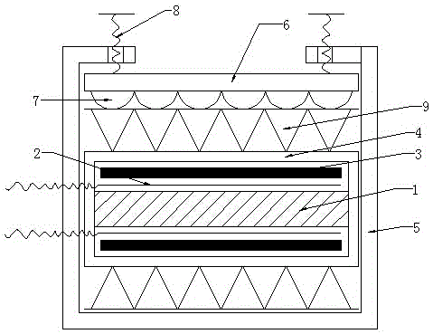
[0015] The preload PTC electric heater of the present invention includes a PTC element 1, and the PTC element 1 is preferably a PTC ceramic sheet. The outer periphery of the electrode 2 is wrapped with an insulating film 3 and then pressed into a square tube 4 to form the main body of the electric heater. The square tube 4 is preferably an aluminum alloy square tube, and also includes a frame body 5. Inside the frame body 5, there is also a pressing plate 6 located between the frame body and the square tube 4 of the main body of the electric heater. The pre-tightening bolt 8, the frame body 5 is provided with a bolt hole facing the upper part of the electric heater body in the frame, the pre-tightening bolt 8 is pressed on the upper surface of the pressure plate 6 through the bolt hole, and the pressure plate 7 is pressed by the pre-tightening bolt 8. So that the elastic layer of the pressing plate 7 is pressed on the main body of the electric heater, when thermal expansion or...

Embodiment 2

[0017] The preload PTC electric heater of the present invention includes a PTC element 1, and the PTC element 1 is preferably a PTC ceramic sheet. The outer periphery of the electrode 2 is wrapped with an insulating film 3 and then pressed into a square tube 4 to form the main body of the electric heater. The square tube 4 is preferably an aluminum alloy square tube, and also includes a frame body 5. The cross-sectional shape of the frame body 5 It is a C-shaped structure so that the frame body 5 forms an opening, the electric heater main body is arranged in the frame body 5, the heat sink 9 is arranged outside the square tube 4 of the electric heater main body, and the frame body 5 is also provided with The pressure plate 6 between the opening of the frame body and the heat sink 9, the bottom surface of the pressure plate 6 is provided with an elastic layer 7, and also includes a pre-tightening bolt 8 that can compress the upper surface of the pressure plate 6, and both sides ...


PUM


Abstract

The invention discloses a pretightening force PTC electric heater. The electric heater comprises a PTC component, electrodes are applied to the external of the PTC and then led out via power lines, and the PTC component and electrodes are wrapped in an insulating film and then compressed and mounted into an electric heater body formed in a square tube. The electric heater further comprises a frame, the electric heater body is placed in the frame, the frame is internally provided with a pressure plate which is placed between the frame and the electric heater body, the bottom of the pressure plate is provided with an elastic layer, and the elastic layer of the pressure plate compresses the electric heater body so that the square tube can generate elastic deformation to compress and fix the PTC component and the electrodes. According to the structure, the PTC component and the electrodes are always compressed and fixed in the using process via the elastic force of the pressure plate, when expansion with heat, contraction with cold or other problem occur, the square tube can generate elastic deformation to compress and fix the PTC component and electrodes, and the heat efficiency is ensured.

Description

technical field [0001] The invention relates to an electric heater, in particular to a pre-tightening force PTC electric heater. Background technique [0002] The traditional PTC electric heater generally includes a PTC ceramic sheet. The PTC ceramic sheet is attached to the electrode and then the electrode is drawn out. At the same time, the PTC ceramic sheet is wrapped with an insulating film and then inserted into a square tube for compression. The traditional PTC electric heating with this structure is made. In the process of use, there is often a gap between the electrode and the PTC ceramic sheet due to thermal expansion and cold contraction, which reduces the reliability of the contact, increases the resistance, and greatly reduces the thermal efficiency. SUMMARY OF THE INVENTION [0003] The technical problem to be solved by the present invention is to provide a preload PTC electric heater which can improve the contact reliability between the electrode and the PTC,...

Claims


Application Information

Patent Timeline
IPC IPC(8): H05B3/02
Inventor 夏铭宇
Owner JIANGSU YUANZHIYI ELECTRIC
Learn More