
Drive shaft shielding over-the-wall device

A transmission shaft and over-the-wall technology, applied in shielding devices and other directions, can solve problems such as affecting the test accuracy, and achieve the effects of excellent shielding efficiency, low power loss, and stable transmission.

Active Publication Date: 2017-09-12
NORTHERN ENG DESIGN & RES INST CO LTD
View PDF5 Cites 0 Cited by
  • Summary
  • Abstract
  • Description
  • Claims
  • Application Information

AI Technical Summary

Problems solved by technology

However, the electrical equipment in the microwave anechoic chamber, such as the driving motor of the test equipment, lighting fixtures, and electrical control systems will increase the ambient level in the anechoic chamber and affect the test accuracy.

Method used


Image

  • Drive shaft shielding over-the-wall device
  • Drive shaft shielding over-the-wall device

Examples


Embodiment Construction

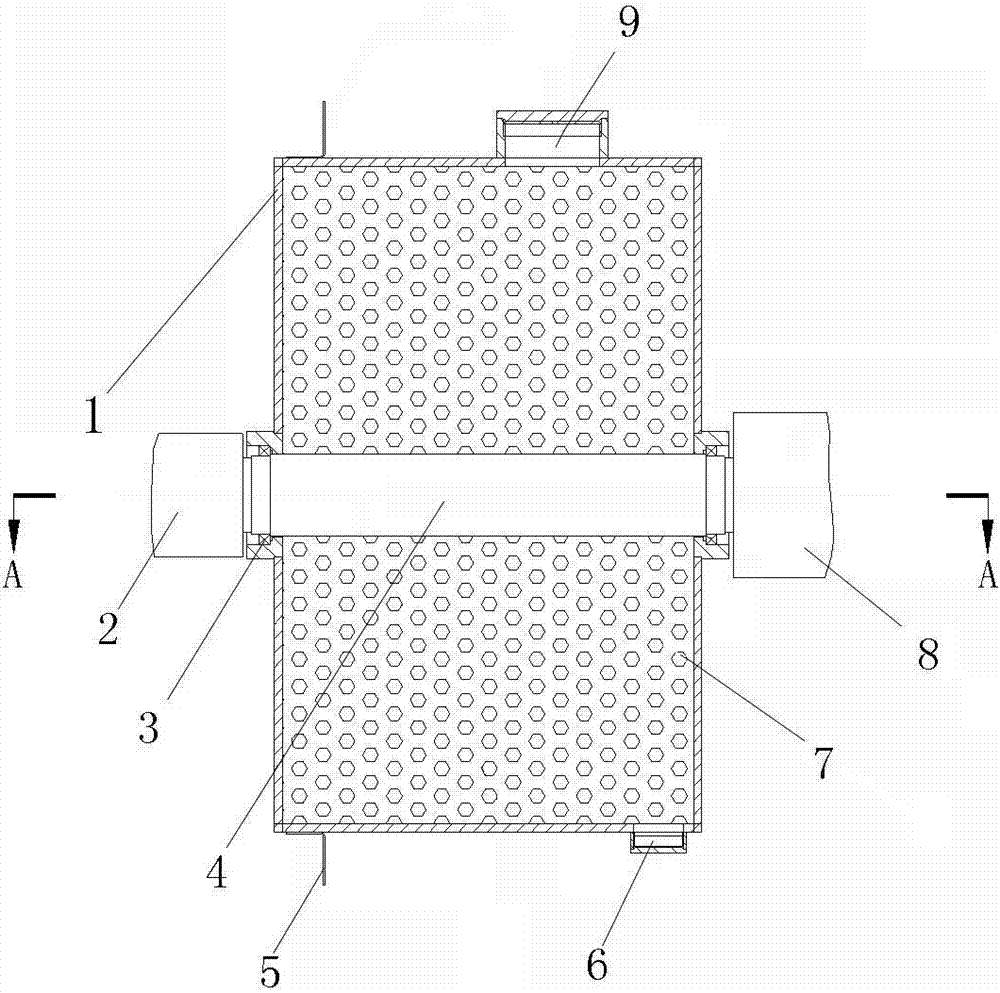
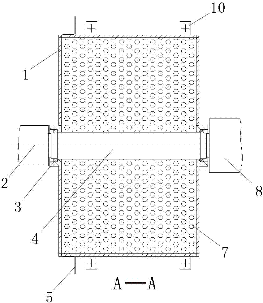
[0016] Depend on figure 1 , 2 As can be seen from the shown embodiment, it includes a box body 1, a spherical electromagnetic wave absorber 7 positioned in the box body 1, a wall-over rotating shaft 4, an output coupling 2, an input coupling shaft 8 and a box body fixing frame; The rotating shaft 4 is installed on the side wall of the box body 1 through the self-aligning bearing 3; one end of the wall passing rotating shaft 4 is connected with the main shaft of the motor reducer installed outside the shielding room through the input coupling 8, and the other end Connect with the main shaft of the turntable installed in the shielding room through the output coupling (2);

[0017] The upper end of the box body 1 is provided with a feed port 9, and the lower end is provided with a discharge port 6, and the feed port 9 and the discharge port 6 are respectively provided with a cover plate, and the feed port 9 is threadedly connected with the cover plate, and the discharge port Th...


PUM


Abstract

The invention relates to a transmission shaft shielded wall-passing apparatus comprises a box body, spherical electric wave absorbers inside the box body, a wall-passing rotating shaft, an output shaft coupling, an input shaft coupling, and a box body fixing rack. The wall-passing rotating shaft is installed on the sidewall of the box body via a self-aligning bearing. One end of the wall-passing rotating shaft is connected with the main shaft of a motor speed reducer installed outside a shielded room via the input shaft coupling. The other end of the rotating shaft is connected with the main shaft of a rotating table installed inside the shielded room via the output shaft coupling. The transmission shaft shielded wall-passing apparatus has advantages of maintaining high-efficient electromagnetic shielding performance of a shield and achieving torque transmission.

Description

technical field [0001] The invention relates to the fields of electromagnetic interference protection and electromagnetic shielding, in particular to a transmission shaft shielding wall-passing device which can realize the torque transmission of the transmission shaft and prevent the leakage of electromagnetic waves. Background technique [0002] With the rapid development of electromagnetic technology, people pay more and more attention to the testing and performance verification of electrical products, and put forward higher requirements for the testing environment. The microwave anechoic chamber can provide environmental protection for the testing of electrical products. However, electrical equipment in the microwave anechoic chamber, such as drive motors of test equipment, lighting fixtures, and electrical control systems, will increase the ambient level in the anechoic chamber and affect the test accuracy. If the driving motor of the test equipment can be placed outsid...

Claims


Application Information

Patent Timeline
Patent Type & Authority Patents(China)
IPC IPC(8): G01R1/18
Inventor 马继庆刘锋王明星王涛张福荣褚伟宾王凯斌
Owner NORTHERN ENG DESIGN & RES INST CO LTD
Learn More