Automatic adjustable variable speed oil pump

An automatic adjustment and variable speed technology, which is applied in the direction of lubricating pumps, engine components, and engine lubrication, can solve problems such as large power consumption, low average engine speed, and failure to adjust the output oil pressure of the oil pump, so as to reduce hydraulic power. and mechanical power, reduce energy loss, and improve work efficiency

Active Publication Date: 2017-11-24
NINGBO SHENGLONG AUTOMOTIVE POWERTRAIN SYSTEM CO LTD
View PDF8 Cites 0 Cited by
  • Summary
  • Abstract
  • Description
  • Claims
  • Application Information

AI Technical Summary

Problems solved by technology

[0003] 1) The output oil pressure of the oil pump is determined according to the speed of the engine, and the speed ratio between the speed of the engine and the shaft of the oil pump is constant. Therefore, it cannot adjust the speed of the shaft of the oil pump when the speed of the engine is constant. It also fails to achieve the purpose of adjusting the output oil pressure of the oil pump;
[0004] 2) When the vehicle is at low speed or idling, the average speed of the engine is low, so the output oil pressure of the oil pump is low, and the output oil volume is also small. However, the engine temperature of the vehicle is high at this time, and the required lubricating oil The demand is large, so it is obvious that the oil supply of the oil pump cannot meet the demand, which will cause the engine to burn out;
[0005] 3) When the engine of the vehicle is running at high speed, the oil pump is prone to cavitation, which affects the service life of the oil pump;
[0006] 4) The torque required to realize the rotation of the shaft of the oil pump comes from the output torque of the engine. Since the speed ratio between the speed of the engine and the shaft of the oil pump is constant, the higher the speed of the shaft of the oil pump, the higher the power consumption required by the engine. The bigger it is, it is not conducive to the demand for energy saving and emission reduction of vehicles

Method used


Image

  • Automatic adjustable variable speed oil pump
  • Automatic adjustable variable speed oil pump
  • Automatic adjustable variable speed oil pump

Examples


Embodiment Construction

[0022] The present invention will be described in further detail below in conjunction with the accompanying drawings and specific embodiments.

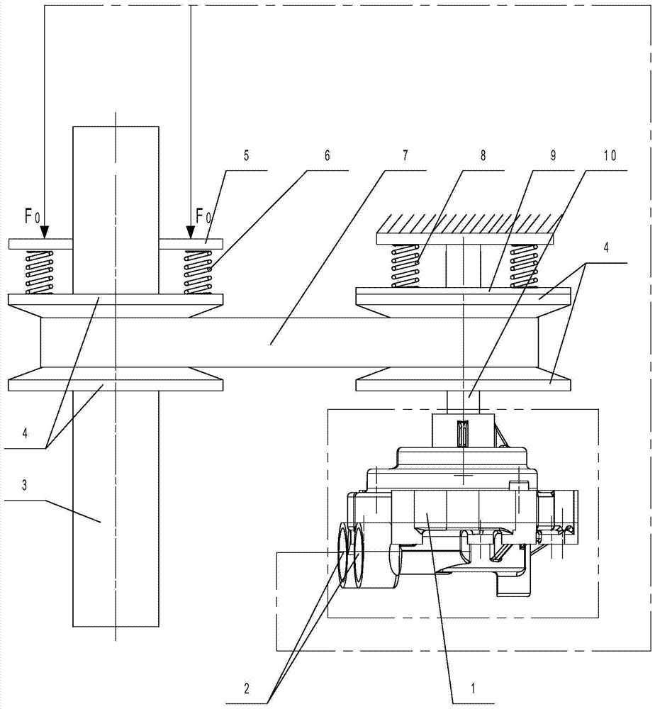
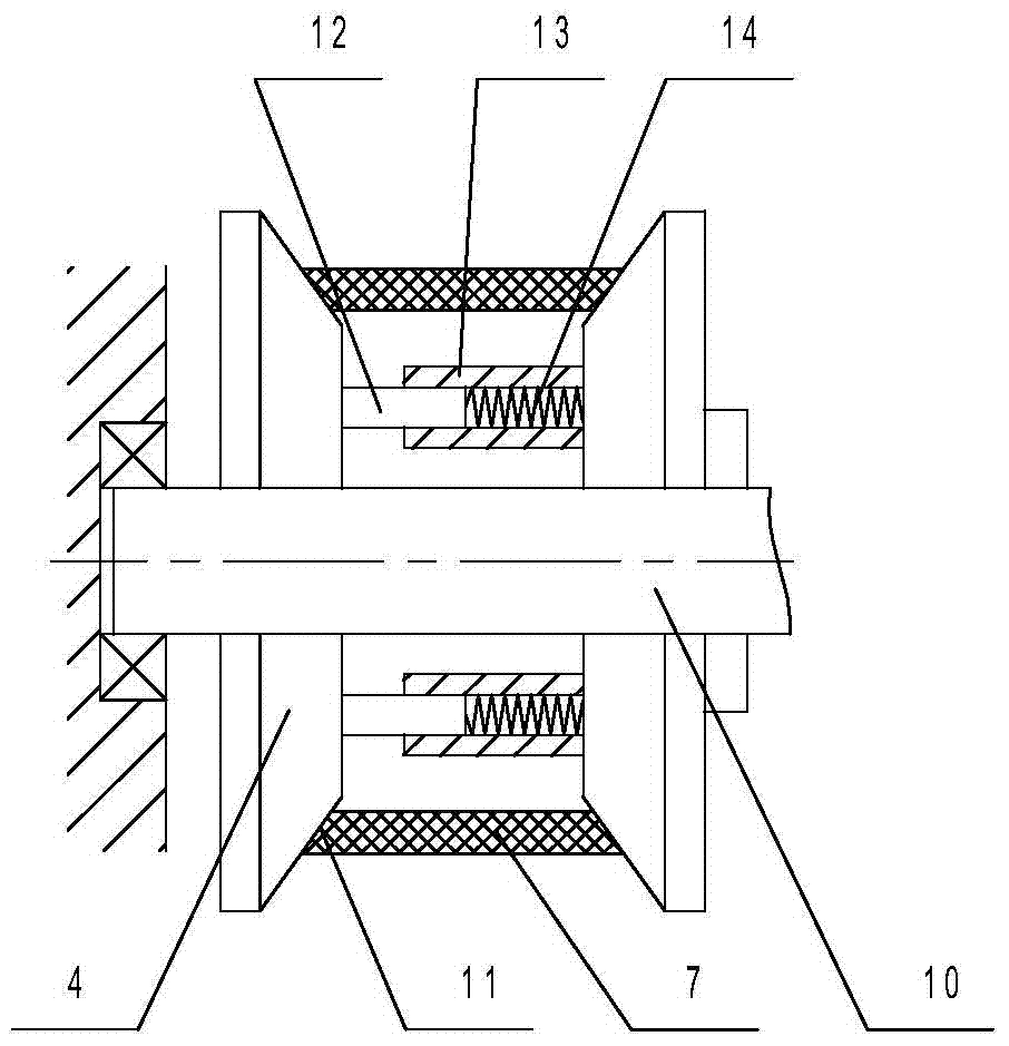
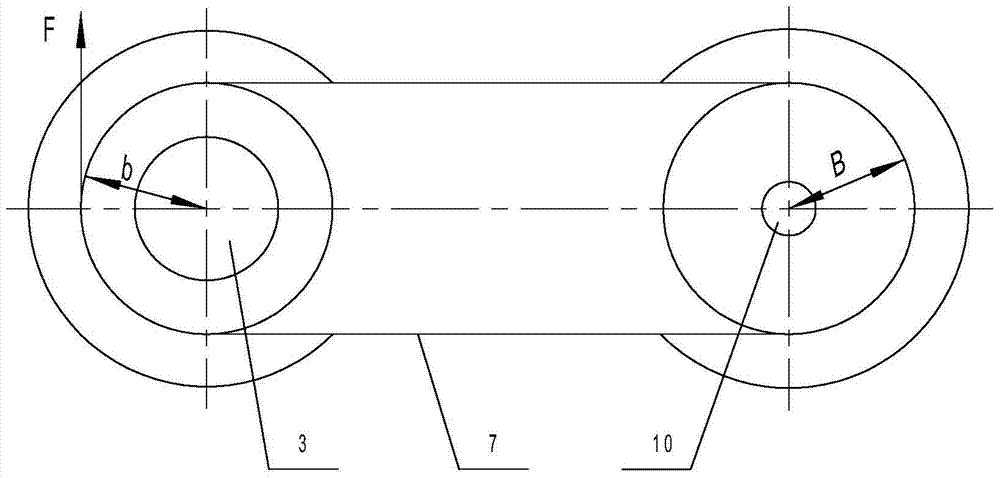
[0023] Depend on figure 1 It can be seen from the schematic structural diagram of the self-adjusting variable speed oil pump of the present invention that it includes an oil pump main body 1 with a rotating shaft 10 and a power output shaft 3 of an engine connected to the rotating shaft 10 through a transmission mechanism. Service port 2 for each lubrication point. The transmission mechanism includes four single-cone rollers 4 and a belt 7, the four single-cone rollers 4 are two pairs, and the conical surfaces of each pair of two single-cone rollers 4 are opposite. Wherein a pair of single-tapered rollers 4 and rotating shaft 10 circumferential limit and sliding fit, and the distance between the two single-tapered rollers 4 is adjusted by the first distance adjustment mechanism; another pair of single-tapered rollers 4 and the power ...


PUM


Abstract

The invention discloses an automatically adjustable variable speed oil pump, which comprises a rotating shaft (10) of an oil pump main body (1) and a power output shaft (3) of an engine connected through a transmission mechanism; the transmission mechanism includes four single-cone rollers (4 ) and belt (7), four single-cone rollers (4) are two pairs, and the conical surfaces of every pair of two single-cone rollers (4) are opposite and coaxial; wherein a pair of single-cone rollers ( 4) It is limited and slidingly matched with the rotating shaft (10) in the circumferential direction, and the distance between the two single-tapered rollers (4) is adjustable; the other pair of single-tapered rollers (4) and the power output shaft (3) are circumferentially Limiting and sliding fit, the distance between the two single-cone rollers (4) is adjustable; the belt (7) is wrapped around the two pairs of single-cone rollers (4). After adopting the above structure, unnecessary energy loss can be reduced, hydraulic power and mechanical power can be reduced, thereby improving the working efficiency of the engine.

Description

technical field [0001] The invention relates to the technical field of oil pumps, in particular to an automatically adjustable variable speed oil pump. Background technique [0002] When the automobile engine is working, each moving part acts on another part with a certain force, and high-speed relative motion occurs. With relative motion, friction will inevitably occur on the surface of the parts, thereby accelerating wear. Therefore, in order to reduce wear, reduce frictional resistance, and prolong service life, there must be a lubrication system on the engine. The main components of the lubrication system are various equipment such as an oil pump. The function of the oil pump is to increase the oil to a certain pressure and then forcefully send it to the moving surface of each part of the engine. It generally includes a pump cover and a pump body. It is connected with the pump body by screws, and the pump body is equipped with an inner rotor, an outer rotor, a low-press...

Claims


Application Information

Patent Timeline
Patent Type & Authority Patents(China)
IPC IPC(8): F16N13/20
Inventor 洪杰罗玉龙周培良
Owner NINGBO SHENGLONG AUTOMOTIVE POWERTRAIN SYSTEM CO LTD
Why Eureka
Try Eureka