Riveting structure, riveting die, riveting process and air conditioner

A riveting structure and riveting technology, applied in the directions of rivets, forming tools, manufacturing tools, etc., can solve the problems of small separation force between bolts and sheet metal parts, failure to meet mechanical performance requirements, and damage to the surface layer of sheet metal parts. Wide range, easy installation, high processing efficiency

Active Publication Date: 2015-11-18
GREE ELECTRIC APPLIANCES INC OF ZHUHAI
View PDF6 Cites 1 Cited by
  • Summary
  • Abstract
  • Description
  • Claims
  • Application Information

AI Technical Summary

Problems solved by technology

It mainly includes the following defects: 1. There are many process steps, and the installation efficiency is low; 2. The material of the joint part between the bolt and the sheet metal after flanging is less, and the separation force between the bolt and the sheet metal after riveting is small, which cannot reach Meet the mechanical performance requirements; 3. Serious damage to the surface layer of sheet metal parts

Method used


Image

  • Riveting structure, riveting die, riveting process and air conditioner
  • Riveting structure, riveting die, riveting process and air conditioner
  • Riveting structure, riveting die, riveting process and air conditioner

Examples


Embodiment 1

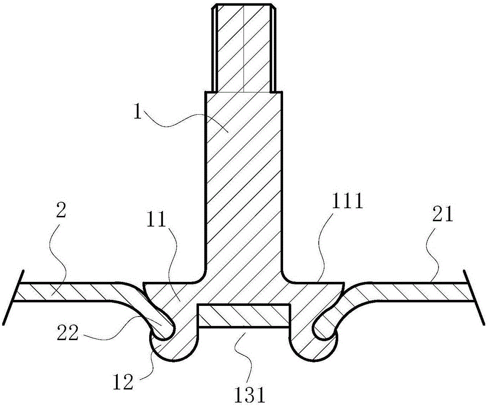
[0039] This preferred embodiment provides a riveting structure. Such as figure 1 As shown, the bolt 1 and the support member 2 are included, and the outer surface 111 of the flange 11 of the bolt 1 is adjacent to the surface 21 of the support member 2 and is in the same plane.

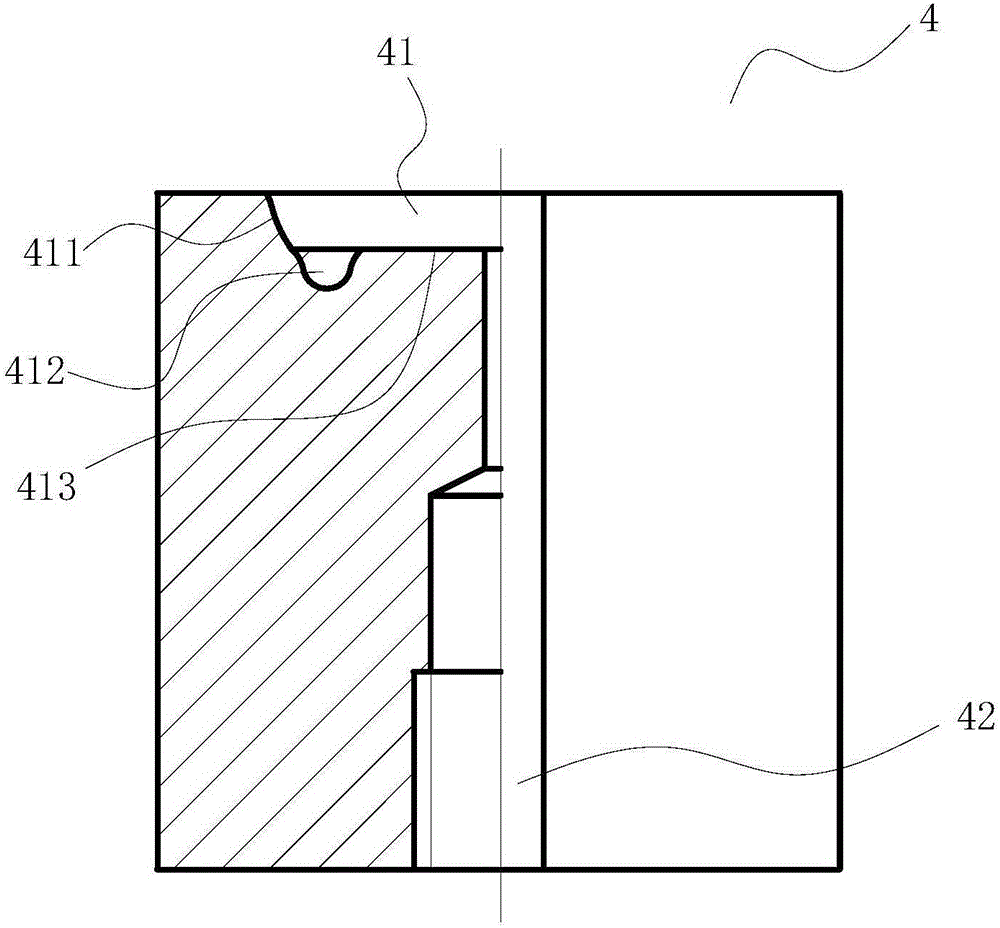
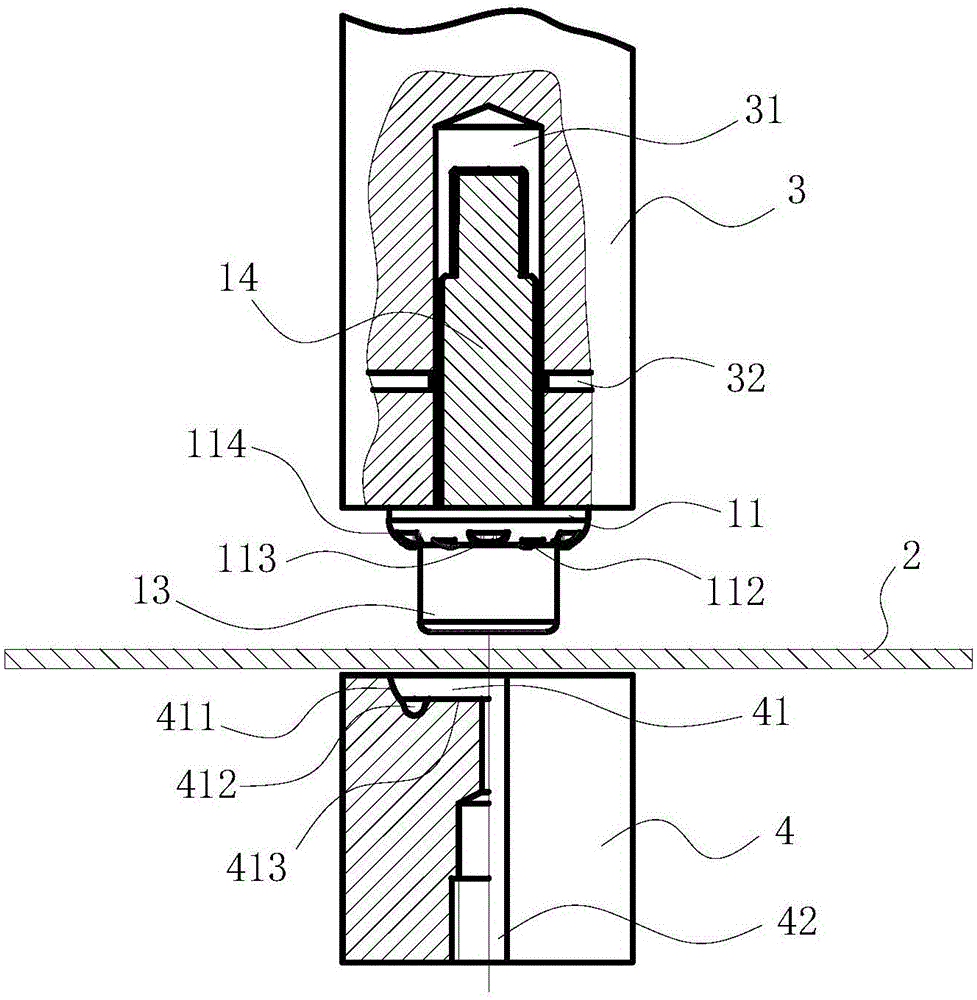
[0040] Such as figure 2 and image 3 As shown, the riveting die used to form the riveting structure includes an upper die 3 and a lower die 4, and the upper die 3 is provided with a cavity 31 for accommodating the screw 14 and a set screw 32 for fixing the screw 14; the lower die 4 A concave molding cavity 41 is formed at the end of the upper body, and the molding cavity 41 is surrounded by a rib 411 , a groove 412 and a bottom surface 413; The lower mold 4 is provided with a residual oil recovery hole 42 for recovering the lubricating oil between the mold and the plate of the support member 2 .

[0041] The riveting process of using the riveting mold to form the riveting structure includes the fo...

Embodiment 2

[0053] This preferred embodiment provides a riveting structure whose structure, processing mold and processing technology are basically the same as those of the preferred embodiment 1. The riveted structure includes a bolt and a support, and the outer side of the flange of the bolt is close to the surface of the support and is in the same plane.

[0054]The difference is that the specific structure of the flange is not limited, whether the bolts form flanging, and the specific shape of the flanging are not limited, as long as the firmness of the riveted structure can be ensured.

Embodiment 3

[0056] This preferred embodiment provides an air conditioner. The air conditioner includes the riveting structure described in the preferred embodiment one or two, which realizes the use of galvanized sheets, galvanized sheets, and galvanized aluminum-magnesium steel sheets (mainly galvanized aluminum-magnesium-coated steel sheets less than or equal to 2mm free of spraying) in the air conditioner. For the application on the chassis, the bolts of the air-conditioning chassis compressor can be riveted and formed at one time, without the need for subsequent spraying treatment, which is energy-saving and environmentally friendly.


PUM


Abstract

The invention discloses a riveting structure, a riveting die, a riveting process and an air conditioner and belongs to the field of air conditioner machining. The problems that an existing riveting structure is low in machining efficiency and the like can be solved. The riveting structure comprises a bolt and a supporting piece. The outer side face of a flange of the bolt and the surface of the supporting piece are adjacent and are located in the same plane. The riveting die comprises an upper die and a lower die. A cavity used for containing a screw is formed in the upper die. A molding cavity recessed inwards is formed in the end of the lower die and defined by a stop edge, a groove and a bottom face, wherein the stop edge inclines outwards from the bottom face. By the adoption of the riveting structure, it can be guaranteed that a rubber pad of a compressor can be horizontally placed, and the compressor can be conveniently installed; a hole does not need to be punched in advance, ribs do not need to be pressed on a board of the supporting piece in advance either, machining efficiency is high, and the surface of the board of the supporting piece is free of damage; and the continuous in-die bolt automatic feeding and riveting process can be achieved and production efficiency is greatly improved.

Description

technical field [0001] The present invention relates to the field of air conditioner processing, in particular to a riveting structure, a riveting mold for forming the riveting structure, a riveting process using the riveting mold to form the riveting structure, and an air conditioner including the riveting structure. Background technique [0002] The compressor is the main component of the air conditioner external unit, and the compressor needs to be installed in the chassis assembly of the air conditioner external unit by means of bolts. [0003] The existing compressor bolt riveting method needs to press ribs and pre-puncher the bolt holes on the sheet metal parts (support parts), then put the bolts into the bolt holes, use the punching machine to drive the upper mold to carry out the bolt flanging riveting, and the bolts Fastened to sheet metal parts (supports). It mainly includes the following defects: 1. There are many process steps, and the installation efficiency is...

Claims


Application Information

Patent Timeline
IPC IPC(8): F16B19/06B21D37/10B21D39/00
CPCB21D37/10B21D39/00F16B19/06
Inventor 朱宏亮彭楚堂王红霞王琳陈学李超男
Owner GREE ELECTRIC APPLIANCES INC OF ZHUHAI
Why Eureka
Try Eureka