
A mold bag grouting device

A technology of grouting device and mold bag, which is applied in the direction of construction and infrastructure engineering, etc. It can solve the problems of difficulty in lower placement, inability to realize water blocking, low success rate, etc., and achieve easy and convenient water plugging and fast water plugging in lower mold bag Water effect, effect of low manufacturing cost

Active Publication Date: 2016-08-31
四川共拓岩土科技股份有限公司
View PDF5 Cites 0 Cited by
  • Summary
  • Abstract
  • Description
  • Claims
  • Application Information

AI Technical Summary

Problems solved by technology

[0002] At present, in the rock mass with a high groundwater flow rate, when conventional cement slurry is used for injection, the cement slurry will be lost with the water flow, and the cement slurry cannot be effectively formed, and the effect of water blocking cannot be realized. The traditional grouting pipe grouting method : The geotextile is processed into a bag shape, and then the grouting pipe is preset. After the grouting pipe and the grouting pipe are bound firmly, the grouting pipe is injected into the bag through the preset grouting pipe to make it expand, so as to achieve water stop or fix the grouting pipe. The purpose is to grout through the grouting orifice pipe to achieve the purpose of sealing the cracks on the rock mass. However, the grouting method of the grouting pipe is not only cumbersome to bind the mold bag, but also has the problem that the mold bag occupies a large space in the grouting hole and is difficult to install. , and the mold bag is easy to damage and fall off, the success rate is low

Method used


Image

  • A mold bag grouting device

Examples


Embodiment Construction

[0011] The present invention will be further described below in conjunction with accompanying drawing, protection scope of the present invention is not limited to the following:

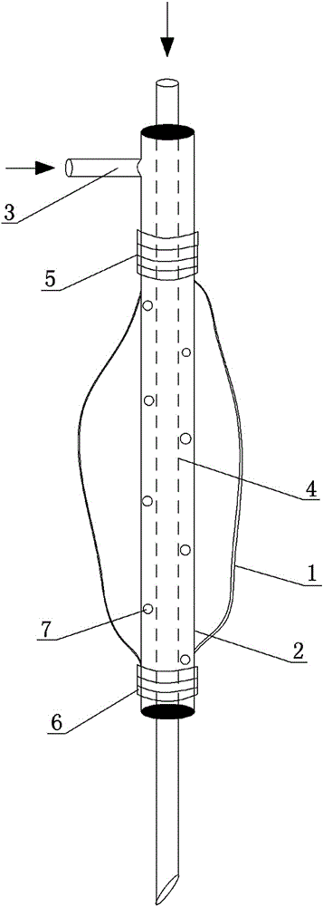
[0012] Such as figure 1 As shown, a mold bag grouting device includes a mold bag 1, an outer pipe 2, a mold bag grouting pipe 3, and a rock mass grouting pipe 4. The rock mass grouting pipe 4 is arranged through the outer pipe 2, and the outer pipe The two ends of 2 and the corresponding rock mass grouting pipe 4 are welded to form a gap between the rock mass grouting pipe 4 and the outer pipe 2, and the outer pipe 2 is inserted into the mold bag 1 from the upper end of the mold bag 1, and the rock mass grouting pipe 4 and the outer pipe 2 are inserted into the mold bag 1. The body grouting pipe 4 is set through the mold bag 1, one end of the mold bag 1 is set on the upper end of the outer tube 2, the other end of the mold bag 1 is set on the lower end of the outer tube 2, and the upper end of the ou...


PUM


Abstract

The invention discloses a mould bag grouting device which comprises a mould bag (1), an outer pipe (2), a mould bag grouting pipe (3) and rock body grouting pipes (4). The rock body grouting pipes (4) penetrate through the outer pipe (2), the two ends of the outer pipe (2) are welded to the corresponding rock body grouting pipes (4), gaps are formed between the rock body grouting pipes (4) and the outer pipe (2), the outer pipe (2) is inserted in the mould bag (1) from the upper end of the mould bag (1), the rock body grouting pipes (4) penetrate through the mould bag (1), one end of the mould bag (1) is arranged at the upper end of the outer pipe (2) in a sleeving mode, the other end of the mould bag (1) is arranged at the lower end of the outer pipe (2) in a sleeving mode, the upper end of the outer pipe (2) is provided with the mould bag grouting pipe (3) communicated with the gaps, a cylindrical face of the outer pipe (2) is further provided with a plurality of through holes (7), and the through holes (7) are communicated with the gaps and an inner cavity of the mould bag (1). The mould bag grouting device has the advantages of being compact in structure, easy to operate and good in water plugging effect, and the mould bag can be arranged downwards easily.

Description

technical field [0001] The invention relates to the technical field of plugging water gushing in holes and rock mass cracks, in particular to a mold bag grouting device. Background technique [0002] At present, in the rock mass with a high groundwater flow rate, when conventional cement slurry is used for injection, the cement slurry will be lost with the water flow, and the cement slurry cannot be effectively formed, and the effect of water blocking cannot be realized. The traditional grouting pipe grouting method : The geotextile is processed into a bag shape, and then the grouting pipe is preset. After the grouting pipe and the grouting pipe are bound firmly, the grouting pipe is injected into the bag through the preset grouting pipe to make it expand, so as to achieve water stop or fix the grouting pipe. The purpose is to grout through the grouting orifice pipe to achieve the purpose of sealing the cracks on the rock mass. However, the grouting method of the grouting pi...

Claims


Application Information

Patent Timeline
Patent Type & Authority Patents(China)
IPC IPC(8): E02D15/04
Inventor 李乔斌钟久安楼日新
Owner 四川共拓岩土科技股份有限公司
Learn More