Cutter tip frequency-response function predicting method based on accurate milling cutter modeling
A technology of frequency response function and prediction method, applied in the direction of measuring/indicating equipment, metal processing machinery parts, metal processing, etc.
- Summary
- Abstract
- Description
- Claims
- Application Information
AI Technical Summary
Problems solved by technology
Method used
Image
Examples
specific Embodiment approach
[0107] The specific implementation of the patent of the present invention is as follows:
[0108] The purpose of the patent of the present invention is to provide a method for predicting the frequency response function of the cutting edge point based on the precise modeling of the milling cutter, so as to solve the problem of accurately modeling the milling cutter and accurately predicting the frequency response function of the cutting edge point. The specific steps are as follows.
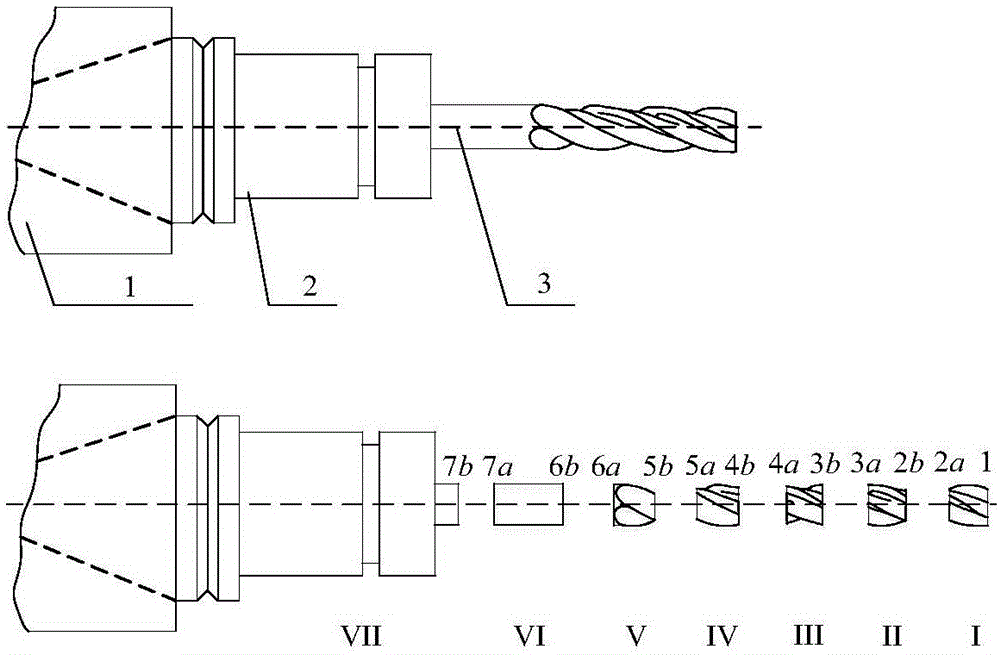
[0109] Step 1: Iffigure 1 As shown, one end of the milling cutter is installed in the tool holder, and the tapered end of the tool holder is installed in the machine tool-spindle matched with the taper at the end of the tool holder, thus forming the machine tool-spindle-tool holder-milling cutter system.
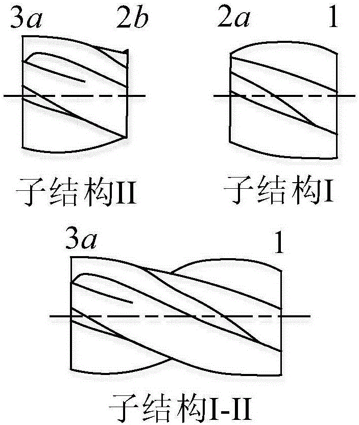
[0110] Step 2: If figure 1 As shown, the machine tool-spindle-tool holder-milling cutter system is divided into four parts: machine tool-spindle-tool holder-partial tool holder, remaining tool ...
Embodiment 1
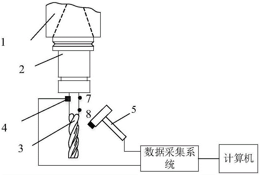
[0191] Embodiment 1: The milling cutter T1 has a diameter of 10mm and a total length of 95mm, and the material is high-speed steel. The distance between points 7 and 8 is 20mm.
[0192] According to the above steps, the predicted value and the measured value of the frequency response function of the cutter point of the milling cutter T1 are obtained. Such as figure 1 Shown, and get the predicted value and measured value of the natural frequency of T1 milling cutter, as shown in Table 1.
[0193] Table 1 Comparison of predicted and measured natural frequencies of T1 milling cutters
[0194]
Embodiment 2
[0195] Embodiment 2: milling cutter T2, a 2-flute milling cutter with a diameter of 10mm and a total length of 100mm, and the material is cemented carbide. The distance between points 7 and 8 is 25mm.
[0196] According to the above steps, the predicted value and the measured value of the frequency response function of the cutter tip point of the milling cutter T2 are obtained. Such as figure 1 Shown, and get the predicted value and measured value of the natural frequency of T2 milling cutter, as shown in Table 2.
[0197] Table 2 Comparison of the predicted value and the measured value of the natural frequency of T2 milling cutter
[0198]
PUM
 Abstract
Description
Claims
Application Information
 - R&D
- Intellectual Property
- Life Sciences
- Materials
- Tech Scout
- Unparalleled Data Quality
- Higher Quality Content
- 60% Fewer Hallucinations
Browse by: Latest US Patents, China's latest patents, Technical Efficacy Thesaurus, Application Domain, Technology Topic, Popular Technical Reports.
© 2025 PatSnap. All rights reserved.Legal|Privacy policy|Modern Slavery Act Transparency Statement|Sitemap|About US| Contact US: help@patsnap.com


