
Ring clamp for connecting electric lines

A power line and ring technology, applied in the installation of cables, electrical components, overhead lines/cable equipment, etc., can solve the problems of difficult completion of meticulous work, delayed work, influence, etc., to improve safety and work efficiency, tightening and the effect of separation work safety

Inactive Publication Date: 2015-11-11
朴澈雄
View PDF0 Cites 0 Cited by
  • Summary
  • Abstract
  • Description
  • Claims
  • Application Information

AI Technical Summary

Problems solved by technology

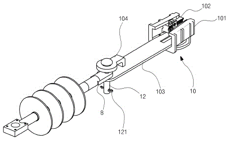
[0012] But, in order to prevent electric shock accident when carrying out above-mentioned operation, the operator all can wear the thick insulating glove, so take out from cotter pin (12) and insert the careful work of hanging pin (121) and be difficult for finishing, can delay Homework and other issues
[0013] In addition, the specification of the hanging pin (121) is relatively small, so that operations such as separating the hanging pin (121) during the operation are greatly affected and may cause problems

Method used


Image

  • Ring clamp for connecting electric lines
  • Ring clamp for connecting electric lines
  • Ring clamp for connecting electric lines

Examples


Embodiment Construction

[0029] The present invention provides a ring clamp for connecting power lines. In order to make the purpose, technical solution and effect of the present invention clearer and clearer, the present invention will be further described in detail below with reference to the accompanying drawings and examples. It should be understood that the specific embodiments described here are only used to explain the present invention, not to limit the present invention.

[0030] refer to Figure 3 to Figure 5 , the specific embodiment of the present invention will be described in detail.

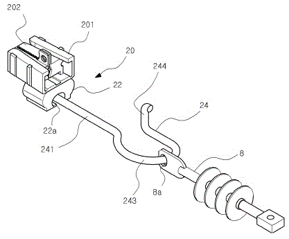
[0031] First, if image 3 As shown, according to the present invention, the ring clamp (20) used to connect the power line is a wedge shape with a narrower width towards the front end, and includes a shell part (201) forming an internal space; A pair of jaws (202) that can slide inside; a supporting plate that can be linked with the above-mentioned jaws (202) installed in the shell part (201); a screw th...


PUM


Abstract

The invention discloses a ring clamp for connecting electric lines. The ring clamp is designed with a wedge shape which becomes narrower at the front part. The ring clamp comprises an external housing part formed inside, a pair of wrenches in the housing part, a support plate interlocking with the wrenches and spiral springs exerting pressure to the support plate. The clamp further comprises a joining part, a connecting hook that can be separated or fastened to the joining part. The connecting hook is connected with an insulator. According to the invention, the separation and the fastening of a clamp to an insulator become safer and it can be done more rapidly. As a result, safety and working efficiency can be improved.

Description

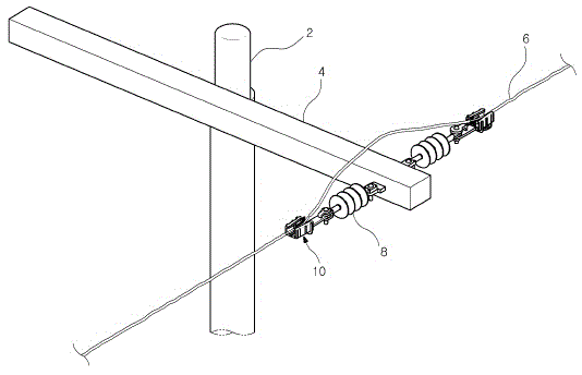
technical field [0001] The invention discloses a ring clamp for connecting power lines, in order to support the power lines on electric poles. Background technique [0002] Under normal circumstances, the power line is sent from the power generation station to the place of use, and usually adopts various loading forms such as ground or underground. Among them, the installation of utility poles is mainly used on the ground. [0003] Depending on the method of using utility poles and supporting power lines, it is necessary to install utility poles in a certain section and erect the supporting power lines on the utility poles to maintain a stable support state. [0004] In addition, an insulating structure is provided between the utility pole and the power line so that electric current cannot pass through the utility pole. This insulating structure is figure 1 As shown, it is composed of an insulator (8) between a transverse support (4) and a power line (6) installed on a uti...

Claims


Application Information

Patent Timeline
IPC IPC(8): H02G7/00H02G1/04
CPCH02G7/02H02G15/22
Inventor 朴澈雄
Owner 朴澈雄
Learn More