
A heat dissipation structure of the current-carrying conductor in the center of an ultra/ultra-high voltage dry bushing

A technology of current-carrying conductors and dry-type bushings, which is applied in the direction of conductors, insulated conductors, and insulated cables. Reliability, wide application range and reasonable heat dissipation structure

Active Publication Date: 2017-08-01
XI AN JIAOTONG UNIV
View PDF5 Cites 0 Cited by
  • Summary
  • Abstract
  • Description
  • Claims
  • Application Information

AI Technical Summary

Problems solved by technology

EHV / UHV dry-type bushings have a high operating voltage level, high power transmission power, large current-carrying capacity and high calorific value of the current-carrying conductor in the center of the bushing, and the problem of uniform heating inside the bushing is prominent. Actual operating experience shows that most dry-type bushings The insulation failure of the pipe is caused by the thermal expansion of the insulation material caused by the high temperature inside the casing
At present, there are not many studies on the heat dissipation structure of the current-carrying conductor in the center of the EHV / UHV dry bushing, and there is no public report on the heat dissipation structure proposed in this patent.

Method used


Image

  • A heat dissipation structure of the current-carrying conductor in the center of an ultra/ultra-high voltage dry bushing
  • A heat dissipation structure of the current-carrying conductor in the center of an ultra/ultra-high voltage dry bushing
  • A heat dissipation structure of the current-carrying conductor in the center of an ultra/ultra-high voltage dry bushing

Examples


Embodiment Construction

[0021] The present invention will be described in detail below in conjunction with the accompanying drawings and embodiments.

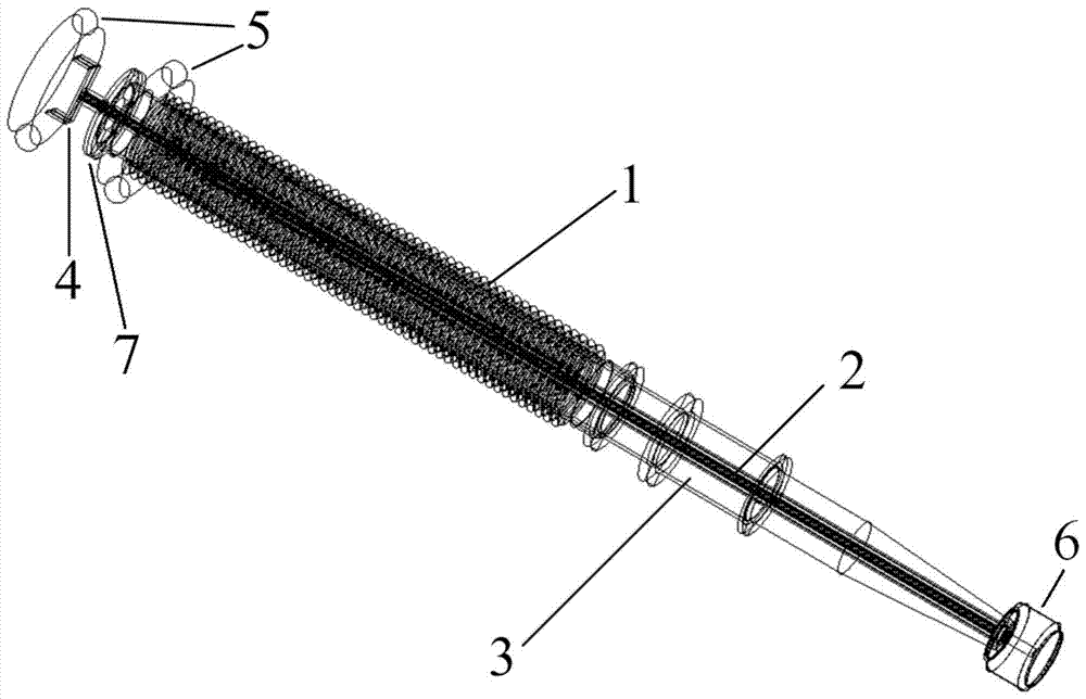
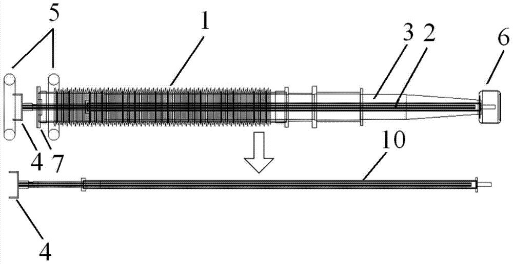
[0022] Such as figure 1 As shown, the EHV / UHV dry bushing is mainly composed of a sheath 1, a current-carrying conductor 2, a core 3, a connecting fitting 4, a pressure equalizing ring 5, a pressure equalizing ball 6, and a cover plate 7. Wherein, the current-carrying conductor 2 is located at the center of the dry bushing, the outer side of the current-carrying conductor 2 is the core 3, the outer side of the core 3 is the sheath 1, and the current-carrying conductor 2 extends out of the cover plate 7 and the end of the bushing. The connecting fittings 4 are connected, the pressure equalizing ring 5 is connected with the connecting fittings 4 through a bracket, and the equalizing ball 6 is installed at the tail of the bushing and connected with the current-carrying conductor 2 .

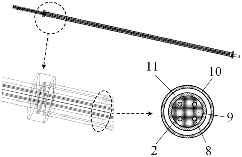
[0023] Such as figure 2 , image 3 As shown, the heat dissipation ...


PUM


Abstract

The invention discloses a heat radiation structure of a central current-carrying conductor of an extra / ultra-high-voltage drying casing pipe. The heat radiation structure comprises a hollow-tube-shaped current-carrying conductor, a liner tube, heat-conducting conductors, and heat-conducting liquid. The liner tube employs a hollow tube type structure and is arranged outside the current-carrying conductor along the direction parallel to the current-carrying conductor; the center of circle of the cross section of the liner tube is overlapped with that of the cross section of the current-carrying conductor; and the liner tube and the current-carrying conductor are separated by air. The heat-conducting conductors are arranged inside the current-carrying conductor along the direction parallel to the current-carrying conductor; and the structures, number, and arrangement mode of the heat-conducting conductors are determined according to the voltage level and operation condition of the casing pipe. The heat-conducting liquid is arranged between the current-carrying conductor and the heat-conducting conductors arranged inside the current-carrying conductor; and the heat generated by the current-carrying conductor is transmitted to the heat-conducting conductors. According to the heat radiation structure, uniformity of the internal temperature distribution of the extra / ultra-high-voltage drying casing pipe can be realized; temperature distribution of the current-carrying conductor, the core, and the sheath and the like can be obviously reduced; and reliability of long-term operation of the extra / ultra-high-voltage drying casing pipe can be improved.

Description

technical field [0001] The invention belongs to the field of electrical insulation structure design and optimization design of super / ultra-high voltage AC and DC transmission equipment, and in particular relates to a heat dissipation structure of a current-carrying conductor in the center of a super / ultra-high voltage dry-type bushing. Background technique [0002] EHV / UHV dry-type bushings are subjected to full voltage, full current and strong mechanical loads during long-term operation, and there are high electrical, thermal and mechanical stresses inside. The electrical and thermal properties of EHV / UHV dry-type bushings affect each other, and the electrical insulation failure of bushings in actual operation is directly related to its thermal properties. EHV / UHV dry-type bushings have a high operating voltage level, high power transmission power, large current-carrying capacity and high calorific value of the current-carrying conductor in the center of the bushing, and th...

Claims


Application Information

Patent Timeline
Patent Type & Authority Patents(China)
IPC IPC(8): H02G3/03H01B7/42H01B9/00
Inventor 彭宗仁王青于杨熙
Owner XI AN JIAOTONG UNIV
Learn More