
Power-transformer overall vacuumizing device

A technology of vacuum pumping device and power transformer, applied in transformer/inductor cooling, switchgear, electrical components, etc., can solve the problems of low vacuum degree of transformer oil conservator, reduction of internal insulation of transformer, expansion and rupture of capsule 4', etc. Achieve the effect of preventing air from entering the inside of the transformer, reducing the accident rate, and reducing manpower and material resources

Active Publication Date: 2015-11-11
STATE GRID FUJIAN ELECTRIC POWER CO LTD +2
View PDF8 Cites 8 Cited by
  • Summary
  • Abstract
  • Description
  • Claims
  • Application Information

AI Technical Summary

Problems solved by technology

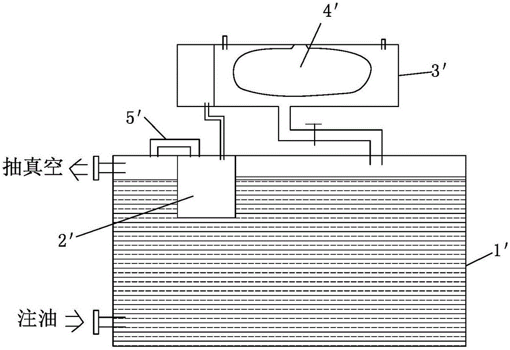
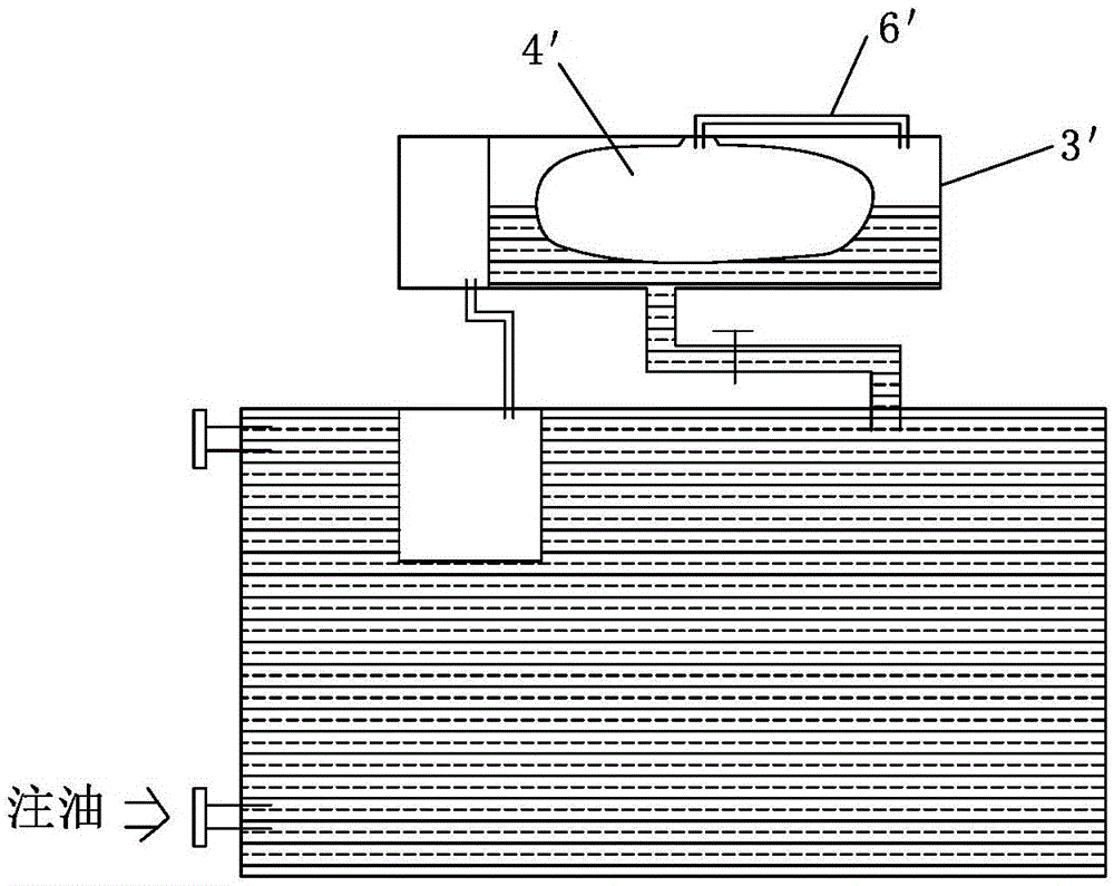
[0006] When the vacuum oiling of the transformer body 1' and the body oil conservator 3' is not completely completed (the capsule oil conservator is usually just over halfway), the vacuum is broken again, and the original capsule 4' is in a compressed state, so remove the vacuuming equipment (remove Connecting pipe 6', such as figure 2 As shown), at this time, it is impossible to continue vacuuming the transformer. If the vacuuming is continued, the capsule 4' will expand and rupture, and the oil can only be filled to the proper oil level.
In addition, the vacuum breaking this time also caused the internal vacuum degree of the transformer oil conservator to be low, and air entered the transformer body, reducing the internal insulation of the transformer.

Method used


Image

  • Power-transformer overall vacuumizing device
  • Power-transformer overall vacuumizing device
  • Power-transformer overall vacuumizing device

Examples


Embodiment Construction

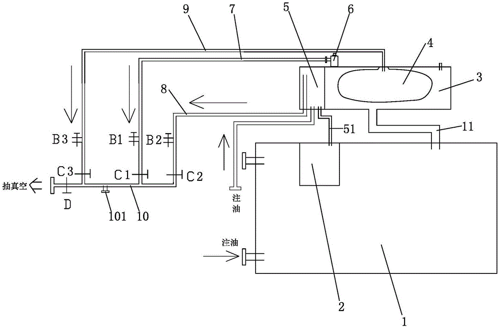
[0031] Examples, see image 3 , Figure 4 As shown, an overall vacuum pumping device for a power transformer of the present invention includes a transformer body 1, a body oil conservator 3, a capsule 4, and an on-load oil conservator 5. The transformer body 1 is connected to the body oil conservator 3 through a connecting pipe 11. The capsule 4 is arranged in the oil conservator 3 of the body, and the on-load oil conservator 5 communicates with the oil chamber 2 of the on-load tap changer in the transformer body 1 through a connecting pipe 51 . A control assembly 6 is installed at the exhaust port 31 of the oil conservator 3 of the body. The control assembly 6 is used to replace the vent plug of the oil conservator 3 of the body in a vacuum state so as to block the exhaust of the oil conservator 3 of the body. The air port 31, the control assembly 6 has a chamber 66 connected to the oil conservator 3 of the body before the vent plug is lowered, and the chamber 66 is connecte...


PUM


Abstract

The invention discloses a power-transformer overall vacuumizing device. The power-transformer overall vacuumizing device comprises a transformer body, a body oil conservator, a capsule and an on-load oil conservator. The transformer body is communicated with the body oil conservator. The capsule is arranged in the body oil conservator. The on-load oil conservator is communicated with an on-load tap-changer oil chamber in the transformer body. A control assembly used for installing a relief plug back in the vacuum state is installed at an exhausting opening of the body oil conservator and comprises a cavity communicated with the body oil conservator before the relief plug is placed down. The cavity is communicated with a first vacuumizing pipe. The power-transformer overall vacuumizing device further comprises a pipe assembly used for vacuumizing the on-load oil conservator, the on-load tap-changer oil chamber and the capsule. According to the power-transformer overall vacuumizing device, recovering in the vacuum undamaged state is achieved through the exhausting opening of the body oil conservator in cooperation with the control assembly, oil injection can be carried out in the state of being not in contact with air completely, insulating oil is not in contact with the air completely, the content of the air in transformer oil is greatly reduced, and the insulation effect inside a transformer is improved.

Description

technical field [0001] The invention relates to an electric power tool, in particular to an integral vacuum pumping device for a power transformer. Background technique [0002] As the central equipment of electric energy transmission and conversion, large power transformer plays an important role in the power grid. The quality of its installation and maintenance process has a significant impact on the operation status of the equipment after it is put into operation, which is directly related to the safe and stable operation of the equipment. [0003] Vacuum pumping and oil filling are important processes in the process of transformer installation and overhaul, and the quality of the process is directly related to the insulation performance inside the transformer. The purpose of vacuuming is to separate the gas inside the transformer and the transformer insulating oil, improve the internal insulation, and prevent the poor vacuum effect of the main transformer from causing a ...

Claims


Application Information

Patent Timeline
IPC IPC(8): H01F27/14H02B3/00
Inventor 兰小建李督林斌陈德枫王茂魁邱桂中
Owner STATE GRID FUJIAN ELECTRIC POWER CO LTD
Learn More