Three-dimensional while-drilling induced polarization rock precise imaging device and method

A technology for stimulating polarization and imaging devices, which is applied in the direction of electric/magnetic detection for well logging records, can solve problems such as time-consuming, low efficiency, and failure to display detection results, so as to improve work efficiency and solve technical problems. Bottleneck, the effect of improving detection efficiency

Active Publication Date: 2015-11-11
山东百廿慧通工程科技有限公司
View PDF6 Cites 9 Cited by
  • Summary
  • Abstract
  • Description
  • Claims
  • Application Information

AI Technical Summary

Problems solved by technology

At the same time, the power supply electrode located in the hole can realize the fine detection of unfavorable geological bodies because it is close to the disaster source such as inrush water, and avoids the interference of metal equipment near the working face, so that the detection accuracy is higher. The current method of drilling detection The main technologies are as follows: [1] Non-drilling-while-drilling resistivity detection method: This method puts the detection device into the drilled hole in advance. Although the array-type measuring electrodes are used, the real-time detection of the drilling pipe is not realized. In the actual detection, it is necessary to stop the drill pipe and take it out so that the detection system can put it into the borehole for detection, which will consume a lot of time and cannot obtain the three-dimensional geological conditions ahead.
[2] With the excitation polarization detection method in the drilling hole: in this method, the detection system is arranged on the drill pipe through the sleeve, in which the power supply electrode A, the observation electrodes M and N, and the auxiliary electrodes A1 an

Method used


Image

  • Three-dimensional while-drilling induced polarization rock precise imaging device and method
  • Three-dimensional while-drilling induced polarization rock precise imaging device and method
  • Three-dimensional while-drilling induced polarization rock precise imaging device and method

Examples


Embodiment Construction

[0054] The present invention will be further described below in conjunction with the accompanying drawings and embodiments.

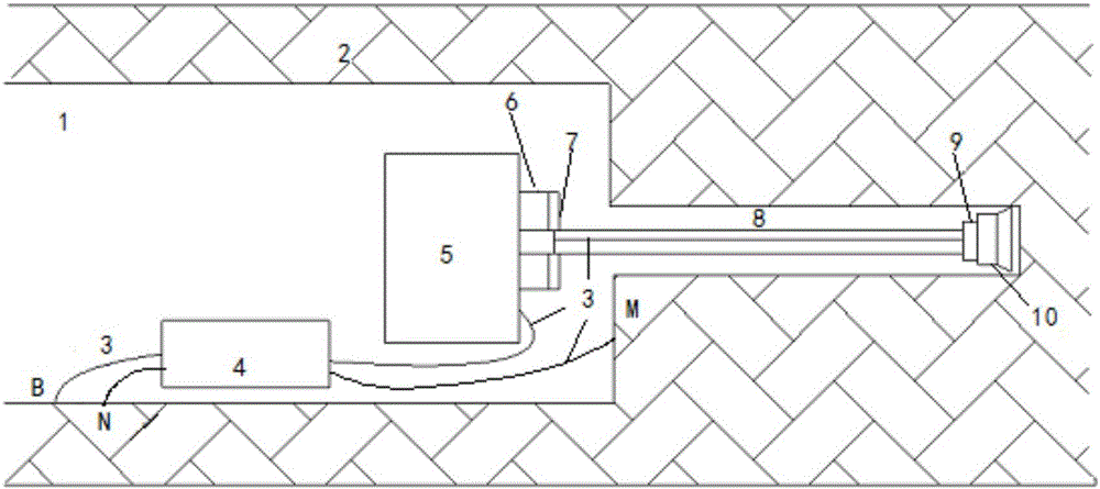
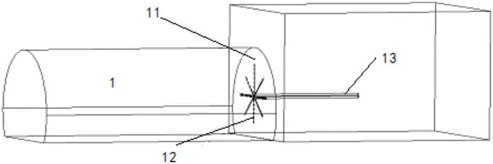
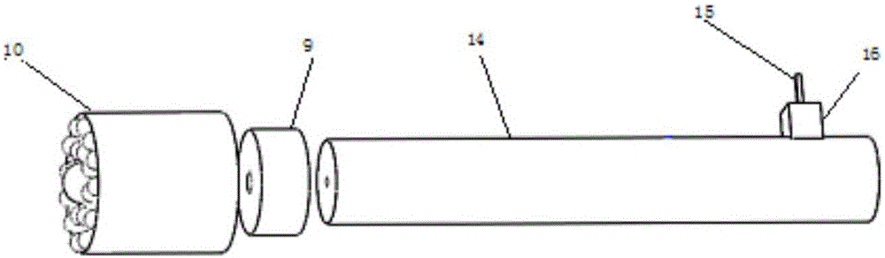
[0055] figure 1 This is a schematic diagram of the detection method and instrument installation structure, which is mainly composed of the power supply system while drilling, the power supply electrode cable 3 and its rotating device, the positioning device of the drill bit 10, the three-dimensional array measuring electrode system, the controller and the real-time inversion imaging system. The drill bit 10 is connected to the drill rod 8 through a double-sided insulation device, the drill rod 8 is connected to the drill rig 5, the conductive slip ring 7 is fixed on the drill rig bracket 6, one end of the cable 3 is connected to the drill bit 10 through a quick joint, and the other end is connected to the drill rod 8 The spring pressing piece 15 at the tail is connected, and the spring pressing piece 15 is connected with the conductive slip ring 7, and ...


PUM


Abstract

The invention discloses a three-dimensional while-drilling induced polarization rock precise imaging device and method. The method is characterized in that a drilling bit in drilling serves as a power supply electrode A which is placed into a hole; a working face is provided with a three-dimensional array measuring electrode; an electrode N and an electrode B are arranged behind the working face; and while-drilling real-time data measurement and real-time three-dimensional inversion imaging are realized, and three-dimensional refined real-time imaging detection of unfavorable geology before the working face is realized. The method can realize while-drilling real-time measurement without interfering drilling construction; the power supply electrode is arranged in the drill hole, so that interference from metal bodies and the like behind a tunnel can be prevented; the drilling bit is served as the power supply electrode creatively; and the advance drilling machine is small in change, and in-hole induced polarization detecting precision and work efficiency are improved.

Description

technical field [0001] The invention relates to a three-dimensional fine imaging device and method for stimulating polarized rock mass while drilling. Background technique [0002] The detection of unfavorable tunnel geology plays an important role in the prevention of tunnel construction disasters. Because the induced polarization method is sensitive to water inrush disaster sources such as water structures, it is widely used in the detection of tunnel disaster sources. For the conventional section with relatively low risk of tunnel construction, the ordinary induced polarization detection method is usually used, and the power supply and measurement electrodes are arranged on the working face or the side wall. Under ideal detection conditions, the inrush water disaster in front of the tunnel working face can be realized source and other adverse geological exploration. Induced polarization is the most electrical detection method, which is greatly affected by the volume effe...

Claims


Application Information

Patent Timeline
IPC IPC(8): G01V3/26
Inventor 李术才聂利超刘斌王传武田明禛郭谦宋杰刘征宇陈磊
Owner 山东百廿慧通工程科技有限公司
Why Eureka
Try Eureka