Flaw detection inspection slide rail device

A flaw detection, slide rail technology, used in bearings, linear motion bearings, shafts and bearings, etc., can solve problems such as cumbersome operations, affecting work efficiency, and safety hazards, reducing labor, avoiding safety hazards, and improving work efficiency. Effect

Inactive Publication Date: 2018-04-06
SHANGHAI INST OF TECH
View PDF7 Cites 0 Cited by
  • Summary
  • Abstract
  • Description
  • Claims
  • Application Information

AI Technical Summary

Problems solved by technology

[0003] The technical problem to be solved by the present invention is to provide a flaw detection inspection slide rail device to solve the cumbersome operation of the existing method, which affects work efficiency and has certain safety hazards

Method used


Image

  • Flaw detection inspection slide rail device
  • Flaw detection inspection slide rail device
  • Flaw detection inspection slide rail device

Examples


Embodiment Construction

[0013] Below in conjunction with specific embodiment, further elaborate the present invention.

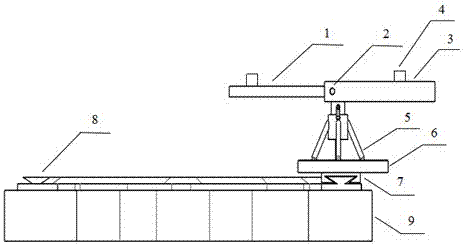
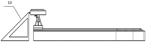
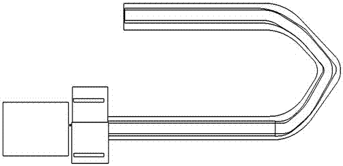
[0014] Such as Figure 1 to Figure 3 As shown, a flaw detection inspection slide rail device, a left support plate 1, a lockable device 2, a right support plate 3, two support bosses 4, a lifting device 5, a support platform 6, a slider 7, and a C-shaped slide rail 8, C-shaped backing plate 9, tank triangle upper and lower frame 10.

[0015] The left support plate 1 is inserted into the right support plate 3 and its position can be fixed by the lockable device 2. Two support bosses 4 are installed above the device to further fix the tank body. Below the platform 6 is that the slide block 7 is connected with the C-shaped slide rail 8 and installed on the C-shaped backing plate 9, and the upper and lower frame 10 of the tank triangle is used in pair with the support plate.

[0016] The left support plate 1 is inserted into the right support plate 3 to fix its position through the l...


PUM


Abstract

The invention relates to a flaw detection sliding rail device. After a left supporting plate is inserted into a right supporting plate, the position of the left supporting plate is fixed with a lockable device, so that tanks of different specifications are tested. The right supporting plate is fixed on a supporting platform through a lifting device. The supporting platform is in sliding connection with a C-shaped sliding rail through a sliding block. The C-shaped sliding rail is mounted on a C-shaped base plate. Two supporting bosses are arranged on the left supporting plate and the right supporting plate. After the left supporting plate is inserted into the right supporting plate, the position of the left supporting plate can be fixed with the lockable device, and the gas storage tanks of different specifications can be tested. The two mounted supporting bosses have the effect of fixing tank bodies. The lifting device on the supporting platform has the effect of increasing or decreasing the tank body flaw detection height so that the tank body flaw detection height can be suitable for flaw detection. The C-shaped sliding rail can be used for moving the gas storage tanks to different testing areas by sliding the sliding block, and thus the gas storage tanks are treated conveniently. A triangular tank-body feeding and discharging bracket and the supporting plates are used in a paired mode so that the tank bodies can be pushed onto or off from the supporting plates through the feeding and discharging bracket. The operating method of the flaw detection sliding rail device is simple, labor force is greatly reduced, and flaw detection work efficiency is improved.

Description

technical field [0001] The invention relates to a flaw detection and inspection slide rail device, in particular to a flaw detection and inspection slide rail device suitable for radiographic flaw detection of circular seams of 1-10m³ tank bodies such as boilers, pressure vessels, and gas storage tanks. Background technique [0002] In the process of using a portable X-ray flaw detector to take pictures, the common method is to manually move the tank body that needs to be taken to the position of the X-ray flaw detector, and then perform flaw detection. After the flaw detection is completed, it will be manually moved to the inspected area. If it is unqualified, it will be moved to the area to be repaired. However, this method is cumbersome and affects work efficiency. Some safety hazards. Therefore, the traditional X-ray flaw detection method has great limitations on the radiation flaw detection work. Contents of the invention [0003] The technical problem to be solved ...

Claims


Application Information

Patent Timeline
Patent Type & Authority Patents(China)
IPC IPC(8): F16C29/02G01N23/04
Inventor 夏轶群曹伟光
Owner SHANGHAI INST OF TECH
Why Eureka
Try Eureka