A kind of uplifting structure and construction method of cement poles for anti-sand soil backfill treatment

A construction method and technology of cement poles, applied in infrastructure engineering, protective devices, buildings, etc., to achieve the effect of increasing uplift resistance, low price, and low material cost

Active Publication Date: 2017-01-25
STATE GRID CORP OF CHINA +2
View PDF6 Cites 0 Cited by
  • Summary
  • Abstract
  • Description
  • Claims
  • Application Information

AI Technical Summary

Problems solved by technology

[0007] It is an urgent requirement to solve the problem of pulling up cement poles in power transmission lines in frost heaving areas by proposing a method for controlling the pulling out of cement poles that is convenient for construction, saves overall costs, increases the resistance to pulling out of shafts, and prevents backfilling of sand.

Method used


Image

  • A kind of uplifting structure and construction method of cement poles for anti-sand soil backfill treatment

Examples


Embodiment 1

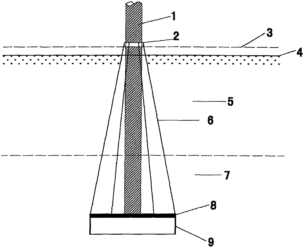
[0033] Embodiment 1: as figure 1 As shown, a kind of anti-sand soil backfill control cement pole pull-up structure, which includes cement pole 1, metal ring 2, metal wire 6, stainless steel plate 8 and annular stainless steel sheet 9, the lower edge of the annular stainless steel sheet 9 is blade-shaped. The bottom of the stainless steel plate 8 is provided with an annular stainless steel sheet 9, the upper edge of the annular stainless steel sheet 9 is welded to the bottom surface of the stainless steel plate 8, the cement rod 1 is vertically arranged above the stainless steel plate 8, and the bottom end of the cement rod 1 is fixed on the stainless steel plate On the top surface of 8, a metal ring 2 is sheathed above the cement rod 1, and several tensioned metal wires 6 are arranged between the metal ring 2 and the stainless steel plate 8, and several metal wires 6 are evenly distributed. One end of the metal wire 6 is welded to the edge of the stainless steel plate 8, and t...

Embodiment 2

[0038] Embodiment 2: Embodiment 1 is a kind of construction method for preventing sand backfilling and controlling the construction of cement rod uplift structure, which includes the following steps:

[0039] (1) dig a cement rod pit at the buried cement rod 1 position, and the depth of the cement rod pit is greater than the thickness of the permafrost layer 5;

[0040] (2) The upper edge of the annular stainless steel sheet 9 is welded to the bottom surface of the stainless steel plate 8 to form a whole;

[0041] (3) The integral body formed by the annular stainless steel sheet 9 and the stainless steel plate 8 is put into the bottom of the cement rod pit, the lower edge of the annular stainless steel sheet 9 is blade-shaped, inserted in the soil at the bottom of the cement rod pit, and the annular stainless steel sheet 9 is vertical Place it so that the stainless steel plate 8 forms a horizontal plane;

[0042] (4) set the metal ring 2 on the cement rod 1, and fix the metal...


PUM


Abstract

The invention discloses a structure for preventing sand backfill and treating concrete pole up-pulling and a construction method thereof. The structure comprises a concrete pole, a fixing ring, a fixing pull line, a fixing base plate and an annular fixing piece. The construction method of the structure comprises the steps that 1, a concrete pole pit is excavated; 2, the upper edge of the annular fixing piece is fixedly connected with the bottom face of the fixing base plate; 3, the annular fixing piece and the fixing base plate are integrally placed into the bottom of the concrete pole pit; 4, the concrete pole is sleeved with the fixing ring; 5, the concrete pole is vertically placed in the concrete pole pit; 6, the fixing pull line is installed; 7, the concrete pole pit is filled with backfill soil and compacted, and therefore construction is finished. According to the structure and the construction method thereof, the concrete pole up-pulling problem caused by soil freezing in winter and melting in summer in the north area of China is fundamentally solved, the structure is simple, construction is convenient, the adopted materials are low in cost, the construction period is short, and the maintenance cost needed for solving the concrete pole up-pulling problem every year is reduced.

Description

[0001] Technical field: [0002] The invention relates to a structure for preventing cement rods from pulling up and a construction method thereof, in particular to a structure for preventing sand backfilling and controlling cement rods from pulling up and a construction method thereof. [0003] Background technique: [0004] In most areas of northern my country, the soil freezes in winter and thaws in summer, which leads to periodic uplifts of some cement poles on transmission lines, with an average maximum uplift of 16cm per year, and tilting and downturning of cement poles in some areas , which seriously threatens the safe operation of the line. Frost heaving of the soil is the prerequisite for the uplift of the cement pole. After the uplift occurs, the unfrozen mud, water and sand around the cement pole root will fall into the cavity to fill the cavity, so that the pole root cannot fall back to the original place after the second year of thawing. It is the root cause of the...

Claims


Application Information

Patent Timeline
Patent Type & Authority Patents(China)
IPC IPC(8): E02D27/35E02D27/42E02D31/14
Inventor 杨倩倩钱文晓肖冰党乐祖向东王瑞郭金刚史昌明孙鹏
Owner STATE GRID CORP OF CHINA
Why Eureka
Try Eureka