Sand core lifting device

A lifting device, sand core technology, applied in the directions of transportation and packaging, cores, load hanging components, etc., can solve the problems of casting inclusions, affecting the surface quality of castings, affecting the surface quality of sand cores or mud cores, etc. Surface quality, avoid the effect of poor surface quality

Active Publication Date: 2017-09-26
KOCEL EQUIP
View PDF5 Cites 0 Cited by
  • Summary
  • Abstract
  • Description
  • Claims
  • Application Information

AI Technical Summary

Problems solved by technology

This method not only affects the surface quality of the sand core or mud core, but also affects the surface quality of the castings made, and even the sand or mud filled in the later stage falls off, causing the castings to be included and scrapped

Method used


Image

  • Sand core lifting device

Examples


Embodiment Construction

[0014] In order to make the technical solution of the present invention more clearly expressed, the present invention will be further described below in conjunction with the accompanying drawings.

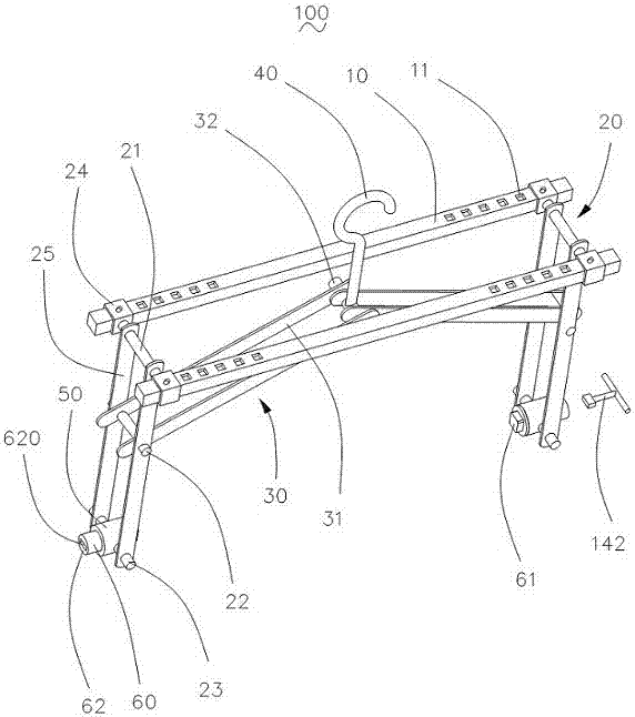
[0015] Please refer to figure 1 , a sand core lifting device 100 according to a preferred embodiment of the present invention is used for clamping and lifting sand cores or mud cores. The sand core lifting device 100 includes two crossbeams 10, two straight tie bars 20, two oblique tie bars 30, a hook 40, two rotor seats 50, two rotors 60 and the rotor 60 supporting The angle adjuster 142. The crossbeams 10 are arranged at intervals, the straight-stay groups 20 are respectively connected to the two ends of the cross-beams 10, one end of each oblique-stay group 30 is pivotally connected to the corresponding straight-stay group 20, and the other end is connected to the suspension. The hooks 40 are connected; the rotor base 50 is connected with the corresponding straight rib group 2...


PUM


Abstract

A sand core hoisting device is used for hoisting sand cores or mud cores. The device comprises two beams, two straight-pulling rib units, two inclined-pulling rib units, a hook, two rotor seats, two rotors and an angle adjuster matched with the rotors. The beams are arranged in a spaced mode, the straight-pulling rib units are connected with the two ends of the beams respectively, one end of each inclined-pulling rib unit is pivoted to the corresponding straight-pulling rib unit, and the other end is connected with the hook. The rotor seats are connected with the corresponding straight-pulling rib units, and the rotors are pivoted to the corresponding rotor seats. By means of the sand core hoisting device, the sand core or mud core surface quality is improved, and the hoisting, cleaning, application and assembly efficiency for small-batch manual production of sand cores or mud cores is improved.

Description

technical field [0001] The invention relates to auxiliary mechanical equipment in the foundry industry, in particular to a sand core lifting device applied to sand cores or mud cores. Background technique [0002] In the existing casting process, when producing sand cores or clay cores, the shape and size of most sand cores or clay cores, the position and size of the lower core during box assembly, and the sand-iron ratio are limited by economic and technical indicators, so it is not allowed to Set lifting lugs and other similar structures on the mold, mud core or sand core; in order to ensure that the sand core or mud core can be assembled under the condition of hoisting, it is necessary to pre-buried hook-shaped lifting rings in the sand core or mud core, and in the When hoisting, the rings are dug out from the sand core or mud core; after the lifting is completed, the "pits" formed by the rings are refilled. This kind of practice not only affects the surface quality of t...

Claims


Application Information

Patent Timeline
Patent Type & Authority Patents(China)
IPC IPC(8): B66C1/10B66C13/08B22C9/10
CPCB22C9/10B66C1/10B66C13/08
Inventor 于苏杭王洪涛
Owner KOCEL EQUIP
Why Eureka
Try Eureka