Improved binding belt

A technology of binding tape and body, applied in the direction of flexible slender elements, packaging, transportation and packaging, can solve the problems of hook deformation, breakage, loose ends of elastic ropes, etc., to achieve good force, firm connection, avoidance of loose effect

Active Publication Date: 2015-11-11
东莞方皓汽车配件有限公司
View PDF7 Cites 1 Cited by
  • Summary
  • Abstract
  • Description
  • Claims
  • Application Information

AI Technical Summary

Problems solved by technology

[0003] At present, the body of the hook of the binding belt seen in the market does not have accommodating holes for fingers to pass through. Users can only buckle their fingers on the hook at the front end of the hook to pull the elastic rope, but this is easy to deform or even break the hook. ; and if you only grasp the retractor body to apply force, your fingers will easily slip off, making it difficult to smoothly pull the retractor to a suitable position
In addition, the pull hook and the elastic rope of the existing binding belt are not integrally injection molded. During use, if the pulling force is large, the end of the elastic rope is easy to loosen from the tail of the pull hook, which brings a lot of trouble to the user.

Method used


Image

  • Improved binding belt
  • Improved binding belt
  • Improved binding belt

Examples


no. 1 example

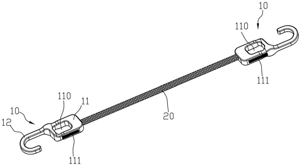
[0029] Such as Figure 1 to Figure 3 As shown, an improved binding belt includes two pull hooks 10 and an elastic rope 20 connecting the two pull hooks 10. The pull hook body 11 of the pull hook 10 is provided with an accommodating hole 110 for fingers to pass through. Through the accommodating hole 110 It is very convenient for the user to buckle the finger in the accommodation hole 110 to exert force on the drag hook 10 during use, and the drag hook 10 will not slip off from the finger. When the user pulls the draw hook 10, the finger surface of the thumb may be placed on the side of the draw hook body 11 of the draw hook 10. In order to further enhance the adhesion between the finger and the draw hook 10, the sides of the draw hook body 11 are respectively provided with anti-slip strips 111, The anti-slip strip 111 is wave-shaped.

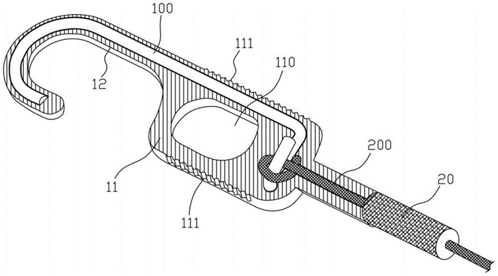
[0030] refer to image 3 , the drag hook 10 of the present invention and the elastic cord 20 are integrally injection-molded, and its specifi...

no. 2 example

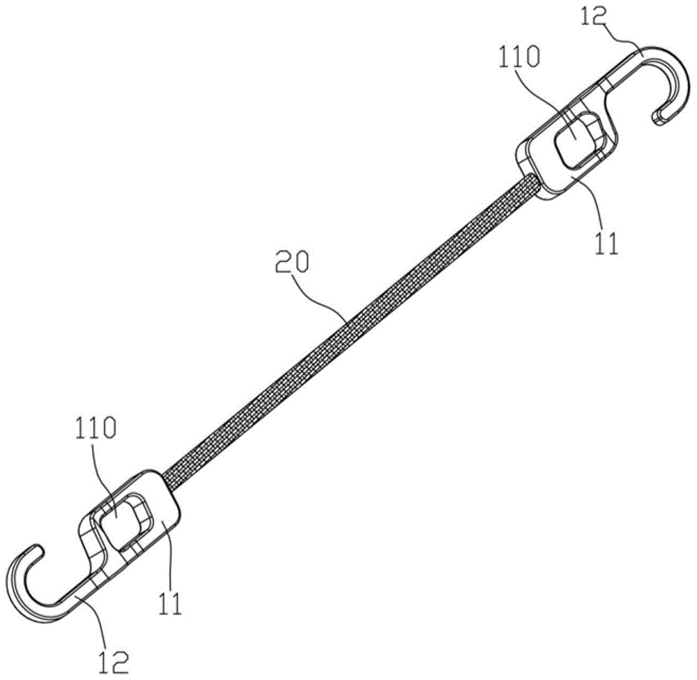
[0032] Such as Figure 4 to Figure 6 , an improved binding belt, comprising two pull hooks 10 and an elastic rope 20 connecting the two pull hooks 10, the pull hook 10 includes a pull hook body 11 and a pull hook part 12, and the two pull hook bodies 11 are provided with a finger The accommodating hole 110 passed through.

[0033] Such as Figure 7 , The improved binding belt also includes a telescopic device 30, the telescopic device 30 includes a drive rod 31, a telescopic rod 32, and a telescopic spring 33, and one end of the drive rod 31 is fixedly connected to the side wall of the telescopic rod 32. The retractable hook body 11 is provided with a telescopic chamber 112 and a driving chamber 113, one end of the telescopic chamber 112 is open, the telescopic spring 33 is arranged at the other end of the telescopic chamber 112, one side of the driving chamber 113 communicates with the telescopic chamber 112, The other side of the driving cavity 113 communicates with the re...


PUM


Abstract

The invention discloses an improved binding belt. The improved binding belt comprises two pull hooks and elastic ropes which are connected with the pull hooks, wherein the rear end of each pull hook body is provided with a containing hole for a finger to penetrate through, by means of the containing holes, a user can conveniently exert force on the pull hooks without slipping. In addition, the pull hooks and the elastic ropes are integrally formed by injection. According to the technical scheme, due to the fact that the rear end of each pull hook body is provided with a containing hole, in the using process, a user can buckle the containing holes with the fingers to pull the elastic ropes, the user can better exert the force, the phenomenon of slipping of the pull hooks can not occur, and the convenience is achieved; the pull hooks and the elastic ropes are integrally formed through the injection, the connection of the pull hooks and the elastic ropes is firmer, and the occurrence of loosening is avoided.

Description

technical field [0001] The invention relates to a binding belt, in particular to a binding belt which is composed of an elastic rope and a drag hook and is used to fix objects. Background technique [0002] Binding belts are widely used in daily life. One of them is composed of elastic rope and pull hooks at both ends. When in use, pull the pull hooks at both ends to make the elastic rope stretch, so that the elastic rope is wound around the object to be fixed. After that, hook the hook at the front end of the retractor to a fixed object. In this way, the elastic rope tightly encloses the object under the action of its own elastic restoring force, thereby achieving the effect of fixing the object. [0003] At present, the body of the hook of the binding belt seen in the market does not have accommodating holes for fingers to pass through. Users can only buckle their fingers on the hook at the front end of the hook to pull the elastic rope, but this is easy to deform or even...

Claims


Application Information

Patent Timeline
Patent Type & Authority Applications(China)
IPC IPC(8): B65D63/16
Inventor 王蓓李方伦
Owner 东莞方皓汽车配件有限公司
Why Eureka
Try Eureka