Expansion joint of contact rail
A technology of expansion joints and contact rails, which is applied in the field of rail transit, can solve the problems of complex structure of contact rails, increased weight of contact rails, and increased production costs, and achieve the effects of simple structure, stable flow diversion, and long service life
- Summary
- Abstract
- Description
- Claims
- Application Information
AI Technical Summary
Problems solved by technology
Method used
Image

Examples
Embodiment 1
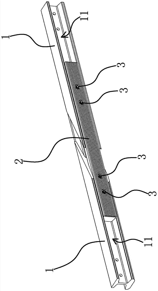
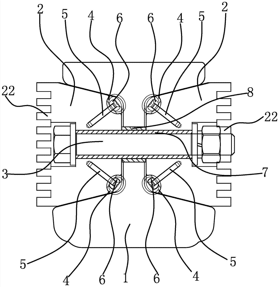
[0039] Such as figure 1 As shown, the contact rail 1 is in the shape of "I", and the two sides of the contact rail 1 are respectively formed with accommodating grooves 11 distributed along the length direction of the contact rail 1. The contact rail 1 is a segmented structure. In this embodiment, two sections The contact rails 1 are located on the same straight line, and an expansion gap is reserved between two sections of the contact rails 1 . The expansion joint of this contact rail includes a connection block 2 , a compression bolt 3 and a spring contact finger 4 .
[0040] Specifically, as image 3 As shown, the connection block 2 is in the shape of a strip and is made of conductive material, and the conductive material can be selected from aluminum, copper or aluminum alloy. The cross section of the connection block 2 is trapezoidal, and the width of the inner end surface of the connection block 2 is smaller than the width of the outer end surface, and both sides are sl...
Embodiment 2
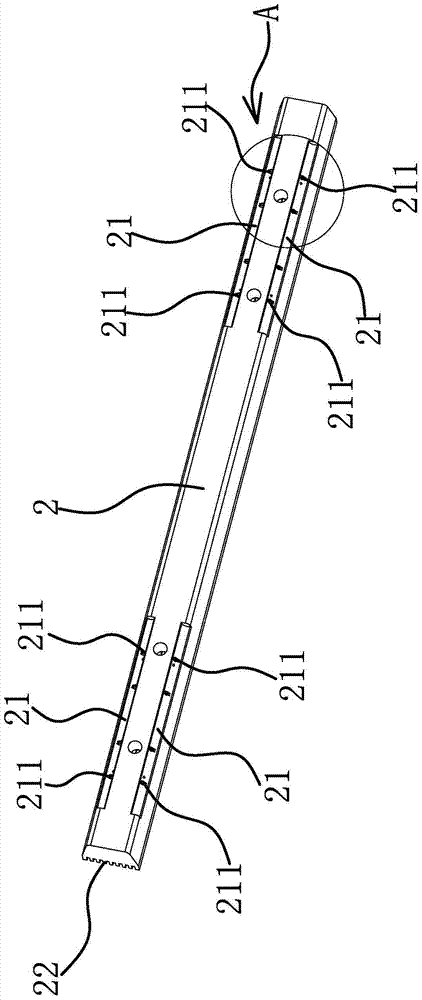
[0051] The technical solution in this embodiment is basically the same as the technical solution in Embodiment 1, the difference is that in this embodiment, such as Figure 9 As shown, the bottom of the receiving groove 11 of one section of the contact rail 1 has an elongated guide hole 12 for the compression bolt 3 to pass through, and the compression bolt 3 can slide along the length direction of the guide hole 12 .
Embodiment 3
[0053] The technical solution in this embodiment is basically the same as the technical solution in embodiment one or embodiment two, the difference is that, as Figure 10 As shown, in this embodiment, the spring contact fingers 4 are fixed on both sides of the bottom of the receiving groove 11 by fixing screws 5 , and the inner end surface of the connecting block 2 has contact grooves corresponding to the positions and shapes of the spring contact fingers 4 . Fixing the spring contact fingers 4 on the busbar 1 also enables an electrically conductive connection of the connection block 2 to the busbar 1 .
PUM
 Abstract
Description
Claims
Application Information
 - Generate Ideas
- Intellectual Property
- Life Sciences
- Materials
- Tech Scout
- Unparalleled Data Quality
- Higher Quality Content
- 60% Fewer Hallucinations
Browse by: Latest US Patents, China's latest patents, Technical Efficacy Thesaurus, Application Domain, Technology Topic, Popular Technical Reports.
© 2025 PatSnap. All rights reserved.Legal|Privacy policy|Modern Slavery Act Transparency Statement|Sitemap|About US| Contact US: help@patsnap.com