
Deformation resistant welding clamp for pipeline assembly and method for preventing pipeline assembly from deformation by utilizing clamp

A welding fixture and anti-deformation technology, applied in the field of thermal processing of pipe fittings, can solve the problems of no effective preventive measures for pipe deformation, baking marks, and difficult to correct pipes, so as to avoid material and surface damage of pipe fittings and meet the scale of enterprises. The effect of production, saving manpower and material resources

Active Publication Date: 2015-11-11
GUANGDONG YONGQIANG ALB INT FIRE FIGHTING ENGINE
View PDF7 Cites 26 Cited by
  • Summary
  • Abstract
  • Description
  • Claims
  • Application Information

AI Technical Summary

Problems solved by technology

[0002] Pipeline components (referred to as "pipe fittings") include main pipe fittings and multiple branch pipe fittings. During the production process, a large number of plasma cutting, welding and other thermal processing at different points are often involved. The resulting deformation of the pipe fittings is almost It is an unavoidable defect, and may even produce "boat-like warping" deformation, and the adjustment of deformed pipe fittings often requires a lot of manpower and material resources, but the effect is not satisfactory
The reason is that the metallographic structure of the workpiece adjusted by local high-temperature fire has changed, resulting in secondary defects such as brittle fracture, cracks, and baking marks on the pipe fittings.
[0003] At present, there are no effective preventive measures for the pipe deformation that occurs during the welding of pipe fittings, and effective prevention cannot be carried out in advance. Only manual or mechanical corrections can be made to the pipes that have undergone welding deformation afterwards.
However, manual or mechanical correction of pipes that have undergone welding deformation requires a lot of manpower, material resources and time, and the larger the pipe, the more difficult it is to make corrections. The resulting pipe fittings have large dimensional errors, which seriously affects the processing quality and quality of pipe fittings. Subsequent assembly and use

Method used


Image

  • Deformation resistant welding clamp for pipeline assembly and method for preventing pipeline assembly from deformation by utilizing clamp
  • Deformation resistant welding clamp for pipeline assembly and method for preventing pipeline assembly from deformation by utilizing clamp
  • Deformation resistant welding clamp for pipeline assembly and method for preventing pipeline assembly from deformation by utilizing clamp

Examples


Embodiment 1

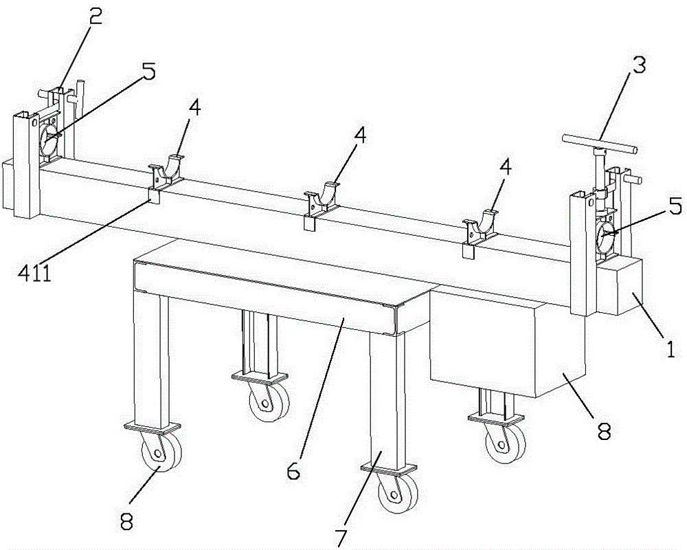
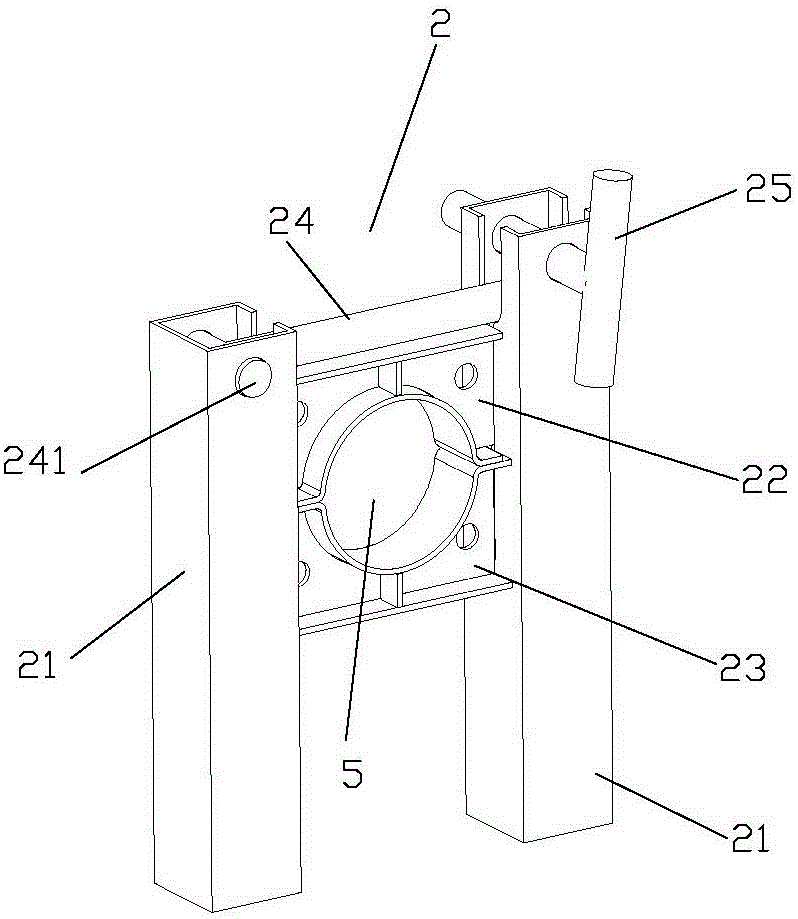
[0058] A pipe fitting anti-deformation welding fixture, such as Figure 1 to Figure 6 As shown, it includes a support 1 , a fixing device 2 arranged at one end of the support 1 for clamping and fixing the pipe, and an adjusting device 3 arranged at the other end of the support 1 for adjusting the clamped position of the pipe.

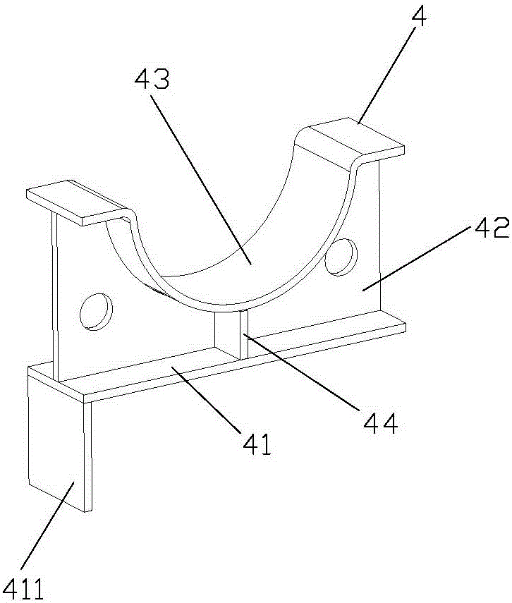
[0059] The support 1 is provided with several anti-deformation limiting blocks 4, the anti-deformation limiting blocks 4 include a bottom plate 41, a support plate 42 and an arc-shaped plate 43 arranged above the bottom plate 41, and the upper end of the support plate 42 is welded to the arc-shaped plate 43 , the lower end of the support plate 42 is welded to the bottom plate 41 , and a reinforcing rib 44 is also arranged between the arc-shaped plate 43 and the bottom plate 41 . The arc of the arc plate 43 is consistent with the arc of the pipe diameter to be processed, which is convenient for placing and clamping the pipe. One end of the bottom plate ...

Embodiment 2

[0068] The method of using a pipe anti-deformation welding fixture in this embodiment to prevent pipe deformation includes the following steps:

[0069] 1) Positioning and angle adjustment of pipe fittings:

[0070] Fix the two ends of the part to be processed of the main pipe fitting or the branch pipe fitting to the fixing device 2 and the adjusting device 3 at both ends of the support 1 respectively, and adjust the angle and position of the pipe fitting through the adjusting device 3;

[0071] 2) Arrange the position of the anti-deformation limit block 4:

[0072] In advance, judge which direction the pipe fitting will deform and move toward the support 1 according to the position where the pipe fitting needs to be subjected to thermal processing such as plasma cutting and welding. After determining the deformation direction of the pipe fitting, make the bending part of the reverse deformation limit block 411 is located on the support 1 on the side opposite to the deformat...


PUM


Abstract

The invention relates to the technical field of hot processing of pipeline assemblies, in particular to a deformation resistant welding clamp for a pipeline assembly and a method for preventing the pipeline assembly from deformation by utilizing the welding clamp. The welding clamp comprises a supporting seat, a fixing device and a regulating device, wherein the fixing device is used for clamping and fixing the pipeline assembly, and the regulating device is used for regulating the clamped position of the pipeline assembly; a plurality of deformation resistant limiting blocks are arranged on the supporting seat; each deformation resistant limiting block comprises a baseplate, a supporting plate and an arc-shaped plate, wherein the supporting plate and the arc-shaped plate are arranged above the baseplate, one end of the baseplate is bent downwards, a bending part for preventing the pipeline assembly from deformation towards a certain direction is arranged at one end of the baseplate in an extending manner, and the bending part is connected with the supporting seat in a clamping manner. Compared with the prior art, the welding clamp disclosed by the invention has the advantages of a deformation resistant function and being simple to operate, deformation towards the certain direction can be effectively avoided in hot processing processes of welding and the like, an operation procedure of deformation correction is omitted, errors of finished pipeline assembly products are reduced, and the processing quality of the pipeline assembly is improved.

Description

technical field [0001] The invention relates to the technical field of pipe fitting thermal processing, in particular to a pipe fitting anti-deformation welding jig and a method for preventing pipe fitting deformation by using the jig. Background technique [0002] Pipeline components (referred to as "pipe fittings") include main pipe fittings and multiple branch pipe fittings. During the production process, a large number of thermal processes such as plasma cutting and welding at different points are often involved. The resulting deformation of the pipe fittings is almost It is an unavoidable defect, and it may even produce "boat-like warping" deformation, and the adjustment of deformed pipe fittings often requires a lot of manpower and material resources, but the effect is not satisfactory. The reason is that the metallographic structure of the workpiece adjusted by local high-temperature fire has changed, resulting in secondary defects such as brittle fracture, cracks, an...

Claims


Application Information

Patent Timeline
Patent Type & Authority Applications(China)
IPC IPC(8): B23K37/053
CPCB23K37/053B23K2101/06
Inventor 张伟豪李振兴张刘军
Owner GUANGDONG YONGQIANG ALB INT FIRE FIGHTING ENGINE
Learn More