a bending machine

A technology of equipment and bending punches, applied in metal processing equipment, feeding devices, positioning devices, etc.

Inactive Publication Date: 2017-04-12
昆山—邦泰汽车零部件制造有限公司
View PDF5 Cites 0 Cited by
  • Summary
  • Abstract
  • Description
  • Claims
  • Application Information

AI Technical Summary

Problems solved by technology

[0002] The plate deforms with the pressure of the bending punch on the bending equipment. The bending equipment in the prior art can only be formed once or the plate is repeatedly stamped in the forming groove to achieve preliminary bending, and then manually The rough part is trimmed, and the existing technology has no bending equipment for automatic fine trimming after preliminary bending

Method used


Image

  • a bending machine

Examples


Embodiment Construction

[0019] The present invention will be specifically introduced below in conjunction with the accompanying drawings and specific embodiments.

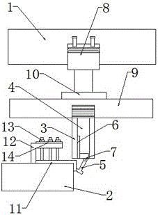
[0020] A bending equipment, comprising: an upper die base 1, a lower die base 2 for placing products, a driving part connected to the upper die base 1, a bending punch 3 connected to the driving part, and set in the bending punch 3 The installation groove 4, the fine-tuning bending assembly set in the installation groove 4, is connected to the lower mold base 2 and presses the fixed assembly of the product; the fine-tuning bending assembly includes: a moving part placed in the installation groove 4, connected to the moving The pendulum clock punch 5 of the piece is connected to the rotating part between the moving part and the pendulum clock punch 5 . As a preference, the moving part is a guide rail 6 placed on the inner wall of the installation groove 4 , and the rotating part is an electronic rotating shaft 7 . In order to allow the fi...


PUM


Abstract

The invention discloses a bending device. The bending device comprises an upper die base, a lower die base used for containing a product, a driving part connected to the upper die base, a bending punch connected to the driving part, a mounting groove formed in the bending punch, a fine-adjustment bending assembly arranged in the mounting groove, and a fixing assembly connected to the lower die base and used for pressing the product. The fine-adjustment bending assembly comprises a moving part placed in the mounting groove, a pendulum clock punch connected to the moving part, and a rotating part connected between the moving part and the pendulum clock punch. After preliminary bending, the bending device can be used for automatically achieving fine trimming. In addition, the product is stably fixed to the lower die base, and thus the situation that the product is shifted due to impact during punching or trimming, and consequently bending precision is reduced is avoided.

Description

technical field [0001] A mold, in particular a bending machine. Background technique [0002] The plate deforms with the pressure of the bending punch on the bending equipment. The bending equipment in the prior art can only be formed once or the plate is repeatedly stamped in the forming groove to achieve preliminary bending, and then manually To trim the rough part, there is no bending equipment for automatic fine trimming after preliminary bending in the prior art. Contents of the invention [0003] In order to solve the deficiencies of the prior art, the purpose of the present invention is to provide a bending equipment that can automatically realize fine trimming after preliminary bending; and the product can be stably fixed on the lower mold base to avoid the product from being damaged due to stamping or trimming. Shock displacement, reducing the accuracy of bending. [0004] In order to achieve the above object, the present invention adopts the following technical...

Claims


Application Information

Patent Timeline
Patent Type & Authority Patents(China)
IPC IPC(8): B21D5/04B21D43/00
Inventor 郑坚雄
Owner 昆山—邦泰汽车零部件制造有限公司
Why Eureka
Try Eureka