
A method for testing the reaction time constant of the main servomotor of a hydroelectric generating set

A main relay and reaction time technology, applied in the direction of instruments, simulators, control/regulation systems, etc., can solve the problem that the simulation models of the turbine and the regulation system do not match, affect the accuracy of the power system, and fail to operate the turbine generator set. The problem of effective measurement of the relay response time constant, etc., to achieve the effect of facilitating accurate modeling and simulation, and improving accuracy

Active Publication Date: 2017-11-28
ELECTRIC POWER SCI RES INST OF GUIZHOU POWER GRID CO LTD
View PDF3 Cites 0 Cited by
  • Summary
  • Abstract
  • Description
  • Claims
  • Application Information

AI Technical Summary

Problems solved by technology

[0003] The technical problem to be solved by the present invention is to provide a test method for the reaction time constant of the main servomotor of the hydroelectric generating set, so as to solve the problem that the test of the governor of the hydroelectric generating set in the prior art cannot effectively test the reaction time constant of the main servomotor of the hydroelectric generating set. The measurement makes the simulation model of the turbine and the regulating system inconsistent with the actual equipment, which affects the accuracy of the stability calculation of the power system and other issues

Method used


Image

  • A method for testing the reaction time constant of the main servomotor of a hydroelectric generating set

Examples


Embodiment Construction

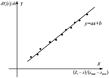
[0024] A method for testing the reaction time constant of a main servomotor of a hydroelectric generating set, comprising the following steps:

[0025] Step 1. Make sure that the working gate of the water inlet of the turbine diversion tunnel is down, the operating oil source of the working gate is closed, the volute drains without water pressure, and the operating oil source of the turbine governor is opened, and the servomotor lock spindle is pulled out; this step is to ensure The safety measures in the subsequent steps are to ensure that there is no water pressure in the water turbine diversion tunnel, penstock and turbine volute by dropping the working gate of the water inlet. When the turbine guide vane moves, the turbine generator set will not rotate.

[0026] Step 2. Short-circuit the "closed" signal line of the main switch of the unit on the governor, so as to simulate the grid-connected operation state of the governor, and switch the governor to the "automatic" operati...


PUM


Abstract

The invention discloses a test method for the reaction time constant of a main servomotor of a water turbine generator set. The method comprises that safe operation conditions are determined; grid-connection operation of a speed regulator is simulated and set in an automatic manner; the proportion amplification multiple of the regulator is set as the minimum, the integration amplification multiple as the minimum, and the differential amplification multiple as the minimum, and a permanent slip coefficient is set as 0; the manual rotating speed and opening degree dead zones of the speed regulator of a water turbine are both set as 0; the minimal displacement in the close direction of main distribution, the maximal displacement in the open direction of main distribution, the minimal open degree of a guide vane, the maximal open degree of the guide vane and a middle position z of main distribution are determined; an open-degree feedback signal of the guide vane is modified to a fixed value; the displacement of main distribution and a curve of open-degree change of the guide vane are determined; the curve is fit; and the reaction time constant of the main servomotor is calculated. The method can be used to solve the problems that the reaction time constant of the main servo motor of the water turbine generator set cannot be effectively measured by speed regulator test of the hydroelectric generating set, and the stability of the power system and the calculation accuracy are influenced.

Description

technical field [0001] The invention belongs to the control technology of a hydroelectric generating set, in particular to a method for testing the reaction time constant of a main servomotor of a hydroelectric generating set. Background technique [0002] Hydropower units play an important role in peak regulation and frequency regulation in the power system. The performance of the speed regulation system of hydropower units directly affects the safe and stable operation of the power grid. In order to ensure the safe and stable operation of power plants and power grids, it is necessary to carry out power system stability Calculation and analysis, therefore, it is necessary to establish a simulation model of the turbine and the regulation system, so that the simulation model matches the actual equipment, and provides an accurate basis for the stability calculation and analysis of the power system. In the process of establishing the simulation model of the hydraulic turbine an...

Claims


Application Information

Patent Timeline
Patent Type & Authority Patents(China)
IPC IPC(8): G05B17/02
Inventor 高晓光苏立唐戢群
Owner ELECTRIC POWER SCI RES INST OF GUIZHOU POWER GRID CO LTD
Learn More