
Outlet unit and air supply device

A technology of air outlet and air outlet, which is applied in the field of air outlet unit and air supply device, which can solve the problems of reduced assembly workability, damage to blade plates, difficulties, etc., to achieve workability, suppress manufacturing costs, and realize control of parts. number effect

Active Publication Date: 2020-02-14
MITSUBISHI ELECTRIC CORP
View PDF17 Cites 0 Cited by
  • Summary
  • Abstract
  • Description
  • Claims
  • Application Information

AI Technical Summary

Problems solved by technology

[0008] In the case of elastically deforming the vane and inserting it into the frame body, it is necessary to apply elastic deformation force to the vane, which may result in a decrease in the workability of the assembly work.
In addition, in the case of excessive elastic deformation, since there is a possibility of damage to the blade plate, it may become difficult to adjust the applied force.
In addition, when the frame body is divided into a plurality of parts, there is a problem that the number of parts increases.
In addition, when a plurality of vanes are provided, difficult work such as sandwiching the plurality of vanes at the same time and assembling the frame body occurs.

Method used


Image

  • Outlet unit and air supply device
  • Outlet unit and air supply device
  • Outlet unit and air supply device

Examples


Embodiment approach 1

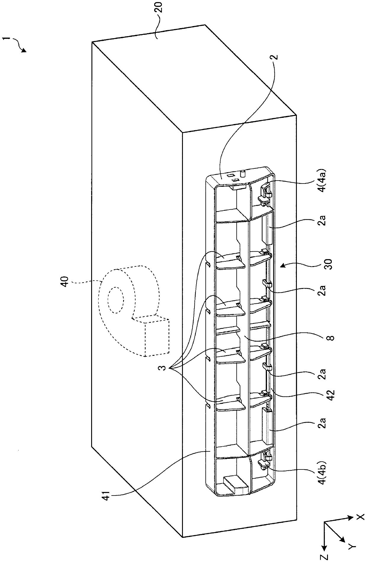
[0031] figure 1 It is a perspective view which shows the schematic structure of the air blower which concerns on Embodiment 1 of this invention. First, the schematic structure of the air blower 1 is demonstrated. The air blower 1 has a housing 20 and an air outlet unit 30 . The frame body 20 has a box shape, and a blower 40 is provided inside. An outlet unit 30 is provided on one surface of the housing 20 . The inside and outside of the housing 20 are communicated through the outlet unit 30 . The air blower 40 provided inside the housing 20 blows air toward the air outlet unit 30 . As a result, air blower 1 blows air from air outlet unit 30 .

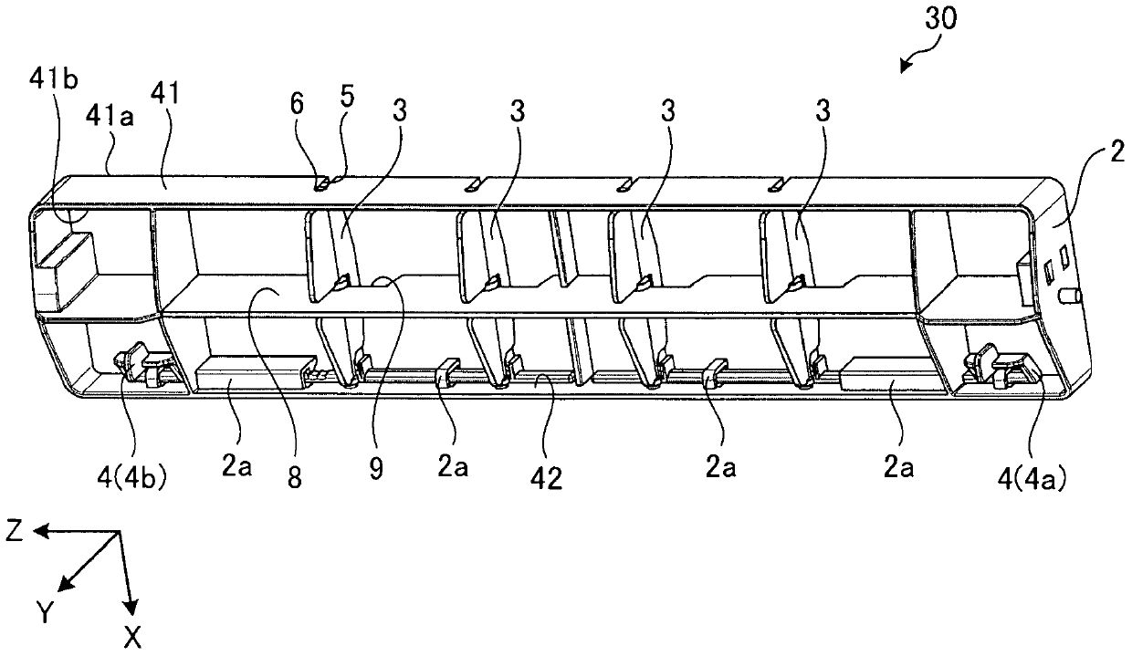
[0032] Hereinafter, the detailed structure of the outlet unit 30 will be described. figure 2 It is a perspective view of the outlet unit 30 . The outlet unit 30 has a frame body 2 , a vane plate 3 , and a link member (link portion) 4 .

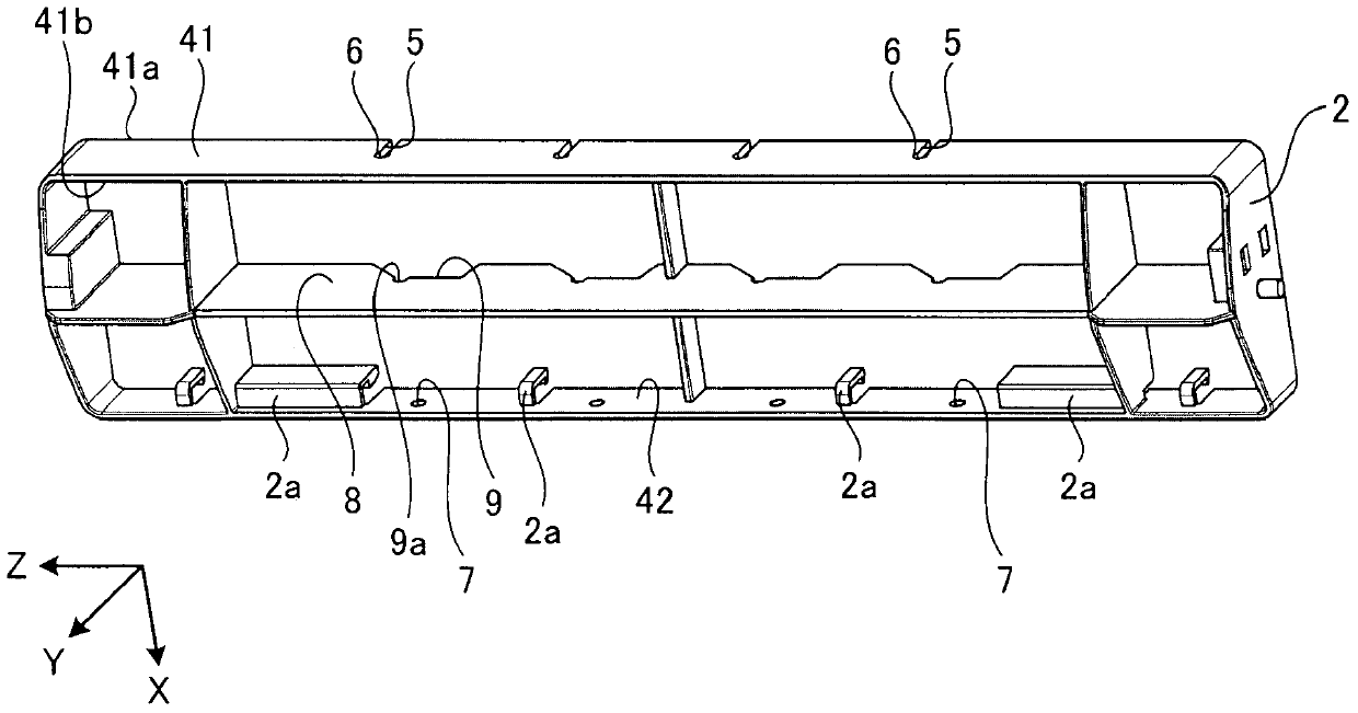
[0033] image 3 It is a perspective view of the frame body 2 . The frame body 2 has a cyl...


PUM


Abstract

The invention provides a blowing outlet unit and an air blowing device. The blowing outlet unit achieves limit of number of parts and reduction of production cost, and increase of operatability of assemblement. The air outlet unit (30) comprising: a frame body (2), which is a cylindrical shape having an opening as a statement of air flowing into the inflow and outflow of the other opening as a testimony air outflow; one blade plate (3), with respect to the frame body (2) relative to each other a first face (41) and a second surface (42), the blade plate are formed by both ends of the support shaft and is rotatable; in the first surface (41), is formed from the edge portion (41a) of the inlet side or outlet side of the edge portion (41b) of the frame side extending slit (5), the blade plate (3) is formed from a shaft portion frame slit (5) of the edge portions (41a, 41b) inserted into the frame slit (5), and the shaft portion is supported rotatably.

Description

technical field [0001] The present invention relates to an outlet unit and an air supply device. Background technique [0002] In air blowers such as wall-mounted or ceiling-mounted dryers and heaters, the installation position of the product varies depending on the structure of the room. Therefore, it is desirable to adjust the air blowing direction from the air outlet according to the installation position of the product. Therefore, a blower outlet unit has been proposed in which a plurality of vanes are rotatably provided at the blower outlet of the air blower, and has a louver mechanism capable of adjusting the blowing direction by changing the posture of the vanes (eg, , refer to Patent Documents 1 and 2). [0003] [Prior Art Literature] [0004] 【Patent Literature】 [0005] [Patent Document 1] Japanese Patent No. 2862165 [0006] [Patent Document 2] Japanese Patent Laid-Open No. 2004-293950 [0007] In the louver mechanisms disclosed in Patent Documents 1 and 2, ...

Claims


Application Information

Patent Timeline
Patent Type & Authority Patents(China)
IPC IPC(8): F24F13/075F24F13/15
Inventor 林俊明安田裕司本木一郎永田雄之泽木孔太郎酒井洋司
Owner MITSUBISHI ELECTRIC CORP
Learn More