
Humidification device for air conditioner, air conditioner and humidification method of air conditioner

A technology for humidifying devices and air conditioners, which is applied in the fields of air conditioners, humidification of air conditioners, and humidification devices for air conditioners. Improve overall performance and work efficiently

Active Publication Date: 2015-11-04
GD MIDEA HEATING & VENTILATING EQUIP CO LTD +1
View PDF5 Cites 22 Cited by
  • Summary
  • Abstract
  • Description
  • Claims
  • Application Information

AI Technical Summary

Problems solved by technology

[0002] It is pointed out in related technologies that the humidifiers of conventional computer room air conditioners mainly rely on manual replenishment and municipal tap water supply. In order to ensure the normal and smooth operation of the railway control signal system, small and medium computer rooms need to be built along the railway stretching thousands of kilometers to provide signal relay. The equipment in the computer room needs to run refrigeration equipment to cool down, and the temperature and humidity control accuracy of the computer room is very high. However, the railway lines are basically far away from residential areas, and some computer rooms are even set up in barren hills and countryside. The environment is very harsh, and the municipal tap water facilities cannot be covered. It is difficult to replenish water, which makes it difficult to humidify the computer room and meet the humidity requirements. At this time, artificial replenishment can only be used to meet the water supply demand of the humidifier. However, the humidifier consumes a large amount of water. Manual replenishment, humidification and water supply are frequent, and the labor cost is high.

Method used


Image

  • Humidification device for air conditioner, air conditioner and humidification method of air conditioner
  • Humidification device for air conditioner, air conditioner and humidification method of air conditioner

Examples


Embodiment Construction

[0034] Embodiments of the present invention are described in detail below, examples of which are shown in the drawings, wherein the same or similar reference numerals designate the same or similar elements or elements having the same or similar functions throughout. The embodiments described below by referring to the figures are exemplary only for explaining the present invention and should not be construed as limiting the present invention.

[0035] In describing the present invention, it should be understood that the terms "upper", "lower", "vertical", "horizontal", "top", "bottom", "inner", "outer" and the like indicate an orientation or The positional relationship is based on the orientation or positional relationship shown in the drawings, which is only for the convenience of describing the present invention and simplifying the description, rather than indicating or implying that the referred device or element must have a specific orientation, be constructed and operated i...


PUM


Abstract

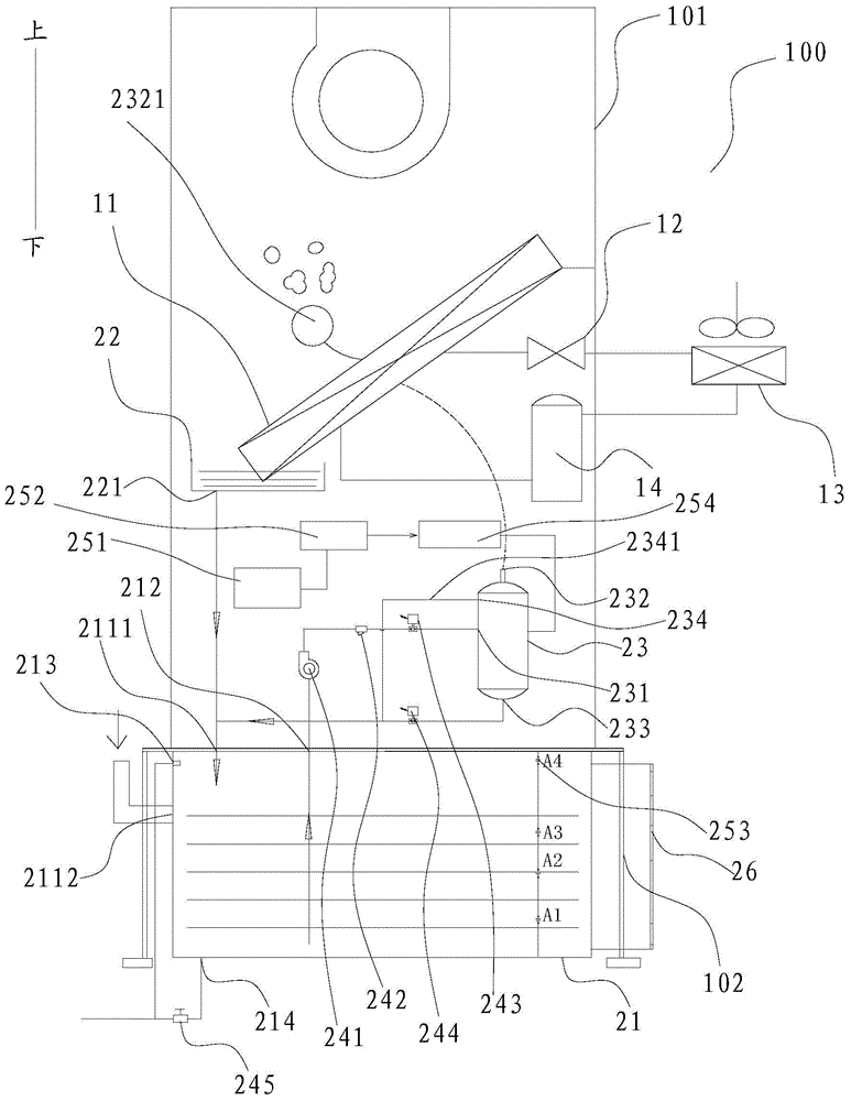
The invention discloses a humidification device for an air conditioner, the air conditioner and a humidification method of the air conditioner. The humidification device comprises a water storage tank, a water collecting disc, a humidifier and a water pump. A water storage tank water supplementing port and a water storage tank water supply port are formed in the water storage tank. A water collecting disc drainage port is arranged on the water collecting disc and communicated with the water storage tank water supplementing port. The humidifier is provided with a water inlet and a steam spray outlet used for spraying steam out and the water inlet is communicated with the water storage tank water supply port. The water pump is connected between the water storage tank water supply port and the water inlet to drive water in the water storage tank to flow into the humidifier. By the adoption of the humidification device for the air conditioner, the water collecting disc is connected to the water storage tank and is then indirectly connected to the humidifier, so that condensed water collected by the water collecting disc from the surface of an evaporator is converted into a water supply source for the humidifier, water resources are effectively used, the frequency of manual water supplementation is reduced, and water cost is saved.

Description

technical field [0001] The invention relates to the field of air conditioners, in particular to a humidifying device for an air conditioner, an air conditioner and a humidifying method for the air conditioner. Background technique [0002] It is pointed out in related technologies that the humidifiers of conventional computer room air conditioners mainly rely on manual replenishment and municipal tap water supply. In order to ensure the normal and smooth operation of the railway control signal system, small and medium computer rooms need to be built along the railway stretching for thousands of kilometers to provide signal relay. The computer room equipment needs to run refrigeration equipment to cool down, and the temperature and humidity control accuracy of the computer room is very high. However, the railway lines are basically far away from residential areas, and some computer rooms are even set up in barren hills and countryside. The environment is very harsh, and the mu...

Claims


Application Information

Patent Timeline
IPC IPC(8): F24F6/18F24F5/00F24F11/02
CPCF24F5/0096F24F6/18F24F11/0008F24F11/89Y02B30/54
Inventor 雷海涛卢文彪胡鸿图
Owner GD MIDEA HEATING & VENTILATING EQUIP CO LTD
Learn More