Rotor impeller and motor with same
A moving impeller and tooth profile technology is applied in the field of moving impellers and motors using the moving impellers, which can solve the problems of increasing the production cost of the vacuum cleaner, and achieve the effects of improving performance, increasing suction air volume, and reducing noise decibels.
- Summary
- Abstract
- Description
- Claims
- Application Information
AI Technical Summary
Problems solved by technology
Method used
Image

Examples
Embodiment 1
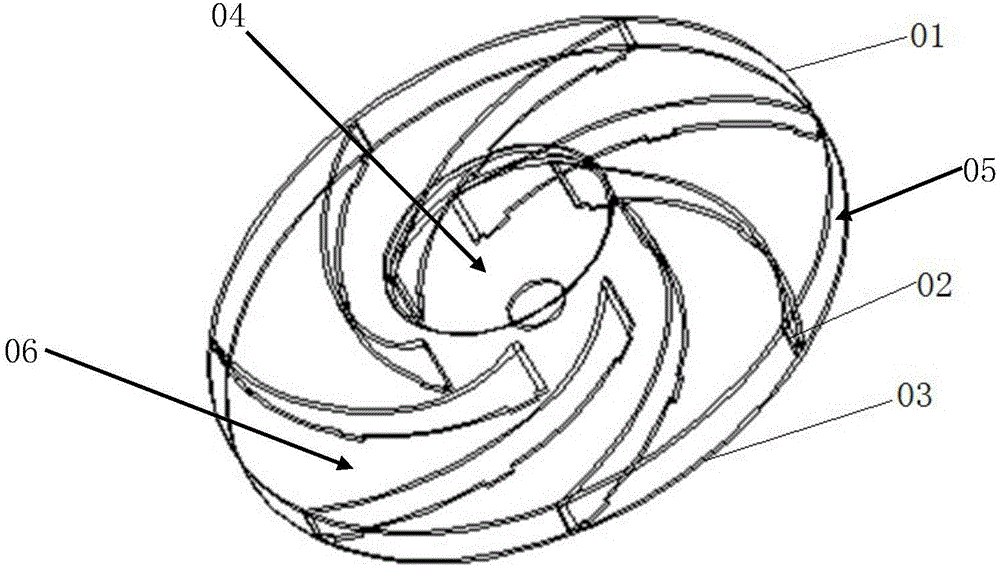
[0079] The utility model relates to a moving impeller, which includes an upper piece, a middle piece and a lower piece, and a tooth-shaped structure is arranged on the outer edge of the upper piece at the wind outlet.
[0080] The number of tooth structures is at least three, and the shape of the tooth structures may be one of rectangle, V shape, semicircle, ellipse and involute shape.
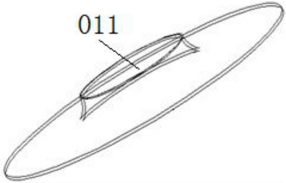
[0081] Please refer to Figure 5 , the structure of the upper piece of the moving impeller provided in this embodiment is shown in the figure, the outer edge 11 of the wind outlet of the upper piece 1 is provided with a toothed structure 13, and the outer edge 12 of the wind inlet of the upper piece 1 is not provided. With a toothed structure, when the vacuum cleaner is working, the moving impeller rotates at a high speed, the air is sucked in from the air inlet, discharged through the suction channel, and is combed smoothly when passing through the toothed structure 13 on the outer edge 11 of...
Embodiment 2
[0086] The utility model relates to a moving impeller, which includes an upper piece, a middle piece and a lower piece, and a tooth-shaped structure is arranged on the outer edge of the middle piece at the wind inlet and / or the wind outlet.
[0087] There is one or more than one tooth structure, and the shape of the tooth structure can be one of rectangle, V shape, semicircle, ellipse and involute shape.
[0088] One of the embodiments of the present invention is that the outer edge 22 of the middle sheet 2 at the air inlet is provided with a toothed structure 23, please refer to Figure 10 , the turbulent flow at the air inlet passes through the toothed structure 14 and is combed smoothly. The shape of the tooth structure 23 can be one of rectangle, V shape, semicircle, ellipse and involute, but the shape of the tooth structure in the present invention is not limited thereto. The number of toothed structures is at least one.
[0089] Please refer to Figure 11 , is another...
Embodiment 3
[0093] The utility model relates to a moving impeller, which includes an upper piece, a middle piece and a lower piece, and a tooth-shaped structure is arranged on the outer edge of the lower piece at the air outlet.
[0094] The number of tooth structures is three or more, and the shape of the tooth structures can be one of rectangle, V shape, semicircle, ellipse and involute shape.
[0095] Please refer to Figure 13 , The structure of the lower piece of the moving impeller provided in this embodiment is shown in the figure, and the outer edge 31 of the lower piece 3 at the outlet of the wind is provided with a toothed structure 32 . Under this embodiment, at least one of the outer edge of the upper sheet at the air outlet, the outer edge of the middle sheet at the air inlet, and the outer edge of the middle sheet at the air outlet can also be provided with a toothed structure. The preferred embodiment of the toothed structures at different positions is that the toothed str...
PUM
 Abstract
Description
Claims
Application Information
 - R&D
- Intellectual Property
- Life Sciences
- Materials
- Tech Scout
- Unparalleled Data Quality
- Higher Quality Content
- 60% Fewer Hallucinations
Browse by: Latest US Patents, China's latest patents, Technical Efficacy Thesaurus, Application Domain, Technology Topic, Popular Technical Reports.
© 2025 PatSnap. All rights reserved.Legal|Privacy policy|Modern Slavery Act Transparency Statement|Sitemap|About US| Contact US: help@patsnap.com