
Eddy flow dehydration plant

A cyclone dehydration and drainage technology, which is applied in the direction of multi-stage series refining process treatment, etc., can solve the problems of limited application, poor dehydration quality and stability, etc., to improve oil purity, improve dehydration efficiency, and dehydration treatment. effect of time reduction

Inactive Publication Date: 2015-11-04
蔡桂钧
View PDF6 Cites 2 Cited by
  • Summary
  • Abstract
  • Description
  • Claims
  • Application Information

AI Technical Summary

Problems solved by technology

[0007] Although the above-mentioned equipment has the advantages of small equipment size and high separation efficiency, its dehydration quality and stability are poor, and its application in oil fields is limited to the field of sewage treatment

Method used


Image

  • Eddy flow dehydration plant

Examples


Embodiment 1

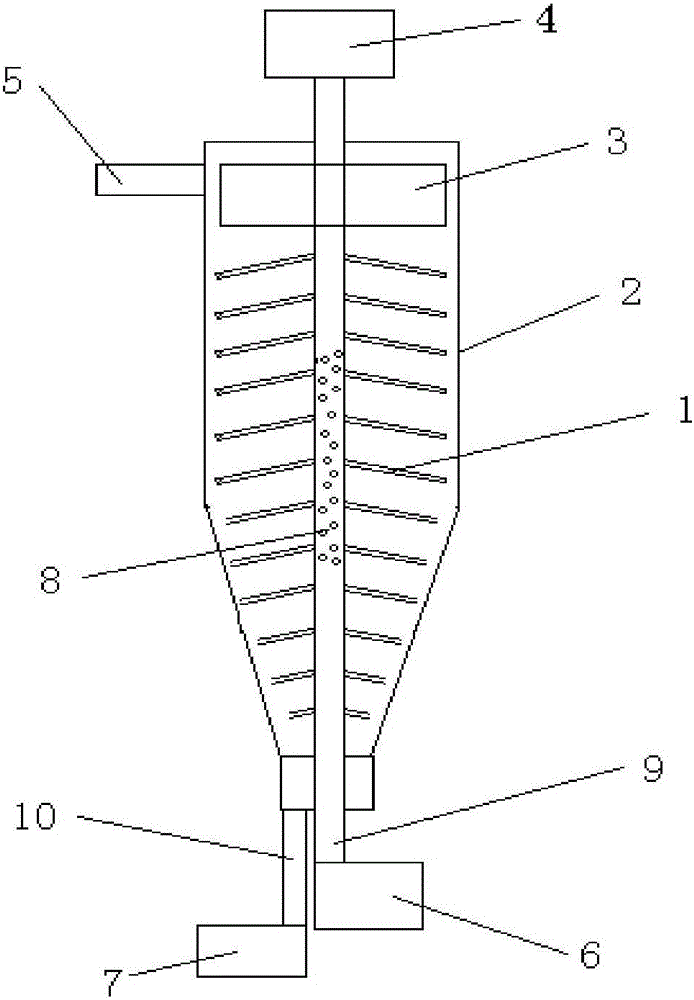
[0026] see figure 1 , a cyclone dehydration device, including a housing 2, a transmission shaft, a movable leaf wheel 3, an electrode plate 1, a liquid inlet pipe 5, an oil collecting pipe 9 and a drain pipe 10, the liquid inlet pipe 5 is arranged on the upper part of the housing, The oil collecting pipe 9 and the drain pipe 10 are arranged at the lower part of the casing, the transmission shaft extends into the casing and connects with the movable impeller 3, the liquid inlet pipe 5 corresponds to the position of the movable impeller 3, and the One end of the oil collecting pipe 5 extends into the housing, the electrode plate 1 is arranged on the oil collecting pipe, and a number of oil collecting pipes are distributed on the oil collecting pipe, and the electrode plate 1 and the oil collecting holes 8 are located in the housing 2, the other end of the oil collecting pipe extends out of the casing.

[0027] The moving leaf wheel 3, the transmission shaft and the section wher...

Embodiment 2

[0036] A swirl dehydration device, comprising a housing 2, a transmission shaft, a movable leaf wheel 3, an electrode plate 1, a liquid inlet pipe 5, an oil collecting pipe 9 and a drain pipe 10, the liquid inlet pipe 5 is arranged on the upper part of the housing, and the The oil collecting pipe 9 and the drain pipe 10 are arranged at the lower part of the casing, the transmission shaft extends into the casing and connects with the moving impeller 3, the liquid inlet pipe 5 corresponds to the position of the moving impeller 3, and the collecting One end of the oil pipe 5 extends into the housing, the electrode plate 1 is arranged on the oil collecting pipe, and a number of oil collecting pipes are distributed on the oil collecting pipe, and the electrode plate 1 and the oil collecting holes 8 are located in the housing 2 Inside, the other end of the oil collecting pipe extends out of the housing.

[0037] The moving leaf wheel 3, the transmission shaft and the section where t...


PUM


Abstract

The invention relates to an eddy flow dehydration plant. The eddy flow dehydration plant comprises a housing, a transmission shaft, a driving page wheel, electrode plates, an liquid inlet pipe, an oil collecting pipe, and a water outlet pipe; the liquid inlet pipe is arranged on the upper part of the housing; the oil collecting pipe and the water outlet pipe are arranged on the lower part of the housing; the transmission shaft is stretched into the housing and is connected with the driving page wheel; the liquid inlet pipe and the driving page wheel are arranged at corresponding positions; one end of the oil collecting pipe is stretched into the housing; the electrode plates are arranged on the oil collecting pipe; a plurality of oil collecting holes are arranged on the oil collecting pipe; the electrode plates and the oil collecting holes are arranged in the housing; and the other end of the oil collecting pipe is stretched out from the housing. According to the eddy flow dehydration plant, eddy flow technology is adopted, oil water separation of crude oil is realized under high speed centrifugal force; dehydrated crude oil is delivered into a machine oil pipe in the housing; oil purity is increased; the eddy flow dehydration plant is small in size, short in dehydration treatment time, and high in dehydration efficiency.

Description

technical field [0001] The invention relates to a mine emulsion crude oil dehydration device, in particular to a cyclone dehydration device. Background technique [0002] At present, the commonly used oil, gas and water separation methods mainly include the following: 1) thermochemical sedimentation method; 2) coarse granulation method; 3) centrifugal force method. [0003] The Chinese patent whose publication number is CN1944586A discloses a kind of sonothermal chemical sedimentation crude oil water separation process. The device used is composed of a carburetor connected by a dosing point through an oil pipeline, a phase mixer and a settling tank; during construction, first use OX-I The type demulsifier passes through the dosing point and adds a demulsifier with a concentration of 100PPM into the oil pipeline to mix with the oil-water mixture in the oil pipeline, and the mixed liquid flows into the carburetor and the phase mixer through the pipeline, and then flows into th...

Claims


Application Information

Patent Timeline
IPC IPC(8): C10G53/02
Inventor 蔡桂钧
Owner 蔡桂钧
Learn More