Control method of power steering for lane departure driving assistance

A driving assistance and lane departure technology, applied in the direction of automatic steering control components, steering mechanisms, steering rods, etc., can solve the problems of vehicle aggravated deviation from the lane, driver's unnaturalness, collision, etc., and achieve the effect of reducing operating load and reducing risk

Inactive Publication Date: 2015-11-04
HUNAN UNIV
View PDF5 Cites 10 Cited by
  • Summary
  • Abstract
  • Description
  • Claims
  • Application Information

AI Technical Summary

Problems solved by technology

[0005] 1. Due to the complexity of the traffic conditions, it is difficult for the lane departure assistance device to accurately and completely identify the safe driving area of ​​the vehicle. While actively applying the auxiliary steering operation to make the vehicle return to the predetermined lane, other accidents may occur, such as collision with the lane Collisions with other objects in
[0006] 2. When it is detected that the driver has an operation intention, or the driver's operation intention conflicts with the assisted steering operation, the decision-making method for exiting the steering assisted operation ignores the driver's wrong steering in emergency conditions and conditioned reflexes Manipulation (that is, the possibility of the steering operation causing the vehicle to aggravate the deviation from the lane) cannot reduce the hazard caused by the driver's wrong steering operation
[0007] 3. The additional auxiliary steering operation drives the steering wheel to turn suddenly, which makes the driver feel unnatural and increases the psychological burden of the driver

Method used


Image

  • Control method of power steering for lane departure driving assistance
  • Control method of power steering for lane departure driving assistance
  • Control method of power steering for lane departure driving assistance

Examples


Embodiment Construction

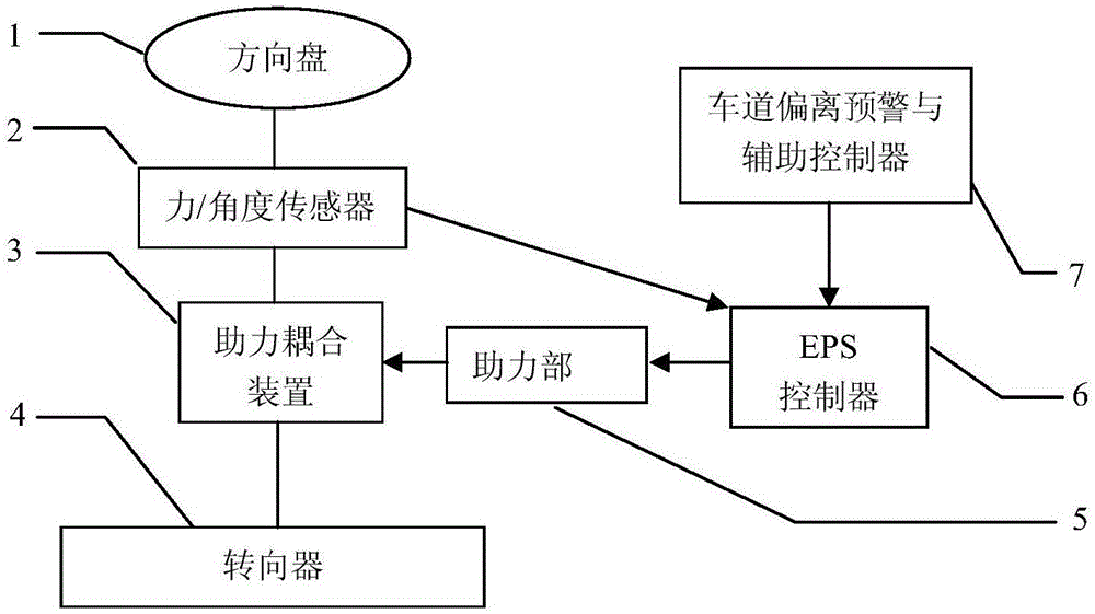
[0020] Embodiments of the present invention will be described below with reference to the drawings. In this embodiment, the power steering device is an electric power steering system (abbreviated as EPS), which consists of an EPS controller (6), a power assist unit (5) (specifically, a power assist motor in this embodiment), a force / angle The sensor (2) and the power coupling device (3) constitute. When the lane departure assistance is not activated, the EPS controller (6) detects the driver’s input torque Td through the force / angle sensor (2), and the booster gain K is equal to Ka determined according to the vehicle’s own driving state such as the vehicle speed (Ka>0) , that is, Ka is the boost gain under normal working conditions, which has nothing to do with the position information of the vehicle on the road. The EPS controller (6) drives the booster part (5), so that the booster part (5) generates a booster torque Ta, and the magnitude of Ta is expressed as:

[0021] Ta...


PUM


Abstract

The invention discloses a control method of power steering for lane departure driving assistance. The control method comprises the following steps: according to the speed of a vehicle and the degree that the vehicle departs from a road, calculating the target steering direction and the angle of a steering wheel, and determining a target of steering assistance; according to a relationship between the steering operation of a driver and the target steering direction and the angle of the steering wheel, determining a power gain coefficient; and enabling a power part to generate a power moment equal to a product of steering force of the driver and the power gain coefficient, and enabling the power moment to be applied on a steering gear through a power coupling device so as to assist the driver in steering. A determination method of the power gain coefficient is characterized in that when the steering direction of the driver is consistent with the target direction, the power gain coefficient is larger than a normal power gain, and when a steering angle is close to a target steering angle, the power gain coefficient gradually decreases to the normal power gain; when the steering direction of the driver is opposite to the target steering, the power gain coefficient in an initial steering stage is smaller than the normal power gain, and the power gain coefficient gradually increases to the normal power gain after a period of time.

Description

technical field [0001] The invention relates to the technical field of vehicle safety, in particular to a steering assist control method when a vehicle deviates from a predetermined lane. Background technique [0002] When the vehicle deviates from the lane due to non-driver's subjective intention, in order to prevent or reduce the damage caused by the lane departure, the lane departure assistance device also actively applies additional steering force or Assisted steering operations, such as steering angle, help the driver to correct the vehicle back to the intended lane. [0003] When the existing lane departure assistance device actively applies an auxiliary steering operation, there are generally two ways. The first way: the vehicle is detected to deviate from the lane, and the steering device actively applies auxiliary steering operations such as torque or cornering to bring the vehicle back to the predetermined lane. When the driver's steering or braking operation is ...

Claims


Application Information

Patent Timeline
Patent Type & Authority Applications(China)
IPC IPC(8): B62D6/00B60W30/12B62D101/00B62D137/00
Inventor 黄智
Owner HUNAN UNIV
Why Eureka
Try Eureka