Valve body manufacturing method

A manufacturing method and valve body technology, applied in the field of valve body manufacturing, can solve problems such as increased equipment cost, energy waste, and limited material performance of the valve body, so as to reduce equipment and production costs, reduce pollution and energy consumption, The effect of improving market competitiveness

Inactive Publication Date: 2015-11-04
ZHONGSHAN XIANGFENG GAS APPLIANCE WARE
View PDF7 Cites 7 Cited by
  • Summary
  • Abstract
  • Description
  • Claims
  • Application Information

AI Technical Summary

Problems solved by technology

[0002] Existing gas valve bodies are usually made of raw materials after die-casting and then grinding and drilling. In the process of die-casting, the raw materials need to be heated, and each manufacturer needs to be equipped with a set of casting equipment, which increases the The cost of equipment and waste of energy, small-scale heating and die-casting process will also produce large industrial pollution, and it will cost a lot of money to deal with these industrial pollution, and in the die-casting process, a single mold can only die-cast one part, The production efficiency is relatively slow, and at present, with the improvement of the degree of automation, the processing speed of the blank is getting faster and faster, and the output speed of the blank in the die-casting process has been difficult to keep up with the processing speed of the blank, thus slowing down the production speed of the valve body
On the other hand, limited to the technological conditions of small-scale die-casting, most of the current valve bodies can only be made of die-casting aluminum such as ADC12. The performance of the valve body is limited and the material properties of die-casting aluminum are difficult to be effectively improved.

Method used


Image

  • Valve body manufacturing method

Examples


Embodiment Construction

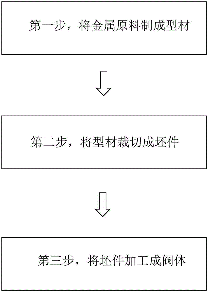
[0015] refer to figure 1 , a manufacturing method of a valve body, comprising the following steps:

[0016] The first step is to heat-melt and extrude the metal raw material into a long profile; this step can be carried out in the existing profile production plant, and the valve body manufacturer does not need to be equipped with additional heat treatment equipment, which reduces equipment and costs. The production cost is improved, the production efficiency is improved, and the pollution and energy consumption are reduced at the same time, which is energy-saving and environmentally friendly.

[0017] In the second step, the profile is cut into several sections of blanks. The shape of the blanks matches the shape of the valve body and is slightly larger than the valve body, which is convenient for processing and can also reduce the waste of materials.

[0018] The third step is to grind and drill the blank to obtain the valve body, and a polishing process can also be added to...


PUM


Abstract

The invention discloses a valve body manufacturing method. The valve body manufacturing method includes the following steps that firstly, raw metal materials are subjected to hot melting and extrusion forming to form long-strip-shaped profiles; secondly, the profiles are cut into a plurality of blanks, wherein the blanks are matched with valve bodies in shape and are slightly larger than the valve bodies; and thirdly, the blanks are ground and drilled to obtain the valve bodies. According to the manufacturing method, due to the fact that the profile forming step can be performed in most of existing profile production plants in a concentrated mode, and valve body manufacturers only need to perform cold machining such as cutting, grinding and drilling on the profiles without additionally arranging heat treatment equipment, the equipment and production cost is reduced, production efficiency is improved, meanwhile, pollution and energy consumption are reduced, and energy conservation and environment protection are archived; besides, due to the fact that existing professional profile production plants have large profile production equipment, raw metal materials such as aviation aluminum with better performance can be adopted for manufacturing the profiles, the performance of the valve bodies can be effectively improved, and the market competitiveness of enterprises can be effectively improved.

Description

technical field [0001] The invention relates to a manufacturing method of a valve body. Background technique [0002] Existing gas valve bodies are usually made of raw materials after die-casting and then grinding and drilling. In the process of die-casting, the raw materials need to be heated, and each manufacturer needs to be equipped with a set of casting equipment, which increases the The cost of equipment and waste of energy, small-scale heating and die-casting process will also produce large industrial pollution, and it will cost a lot of money to deal with these industrial pollution, and in the die-casting process, a single mold can only die-cast one part, The production efficiency is relatively slow, and at present, with the improvement of the degree of automation, the processing speed of the blank is getting faster and faster, and the output speed of the blank in the die-casting process has been difficult to keep up with the processing speed of the blank, thus slowi...

Claims


Application Information

Patent Timeline
IPC IPC(8): B23P15/00
CPCB23P15/001
Inventor 梁健豪
Owner ZHONGSHAN XIANGFENG GAS APPLIANCE WARE
Why Eureka
Try Eureka