
A two-dimensional code scanner sharing fill light and alignment light

A two-dimensional code scanning and fill light technology, applied in electromagnetic radiation induction and other directions, can solve the problems that affect the camera's photo effect, cannot fill light, etc., and achieve the effect of reasonable structure and cost saving.

Active Publication Date: 2018-05-29
FUJIAN LANDI COMML EQUIP CO LTD
View PDF5 Cites 0 Cited by
  • Summary
  • Abstract
  • Description
  • Claims
  • Application Information

AI Technical Summary

Problems solved by technology

The positioning spot of the rectangular frame generated by the light-emitting diode through the shading object or the shading plate plays the role of positioning, which can improve the user's scanning experience, but the positioning spot obtained in this way is on the outer boundary of the camera scanning area and cannot scan the camera. The area has the effect of filling light and will affect the camera's photo effect

Method used


Image

  • A two-dimensional code scanner sharing fill light and alignment light
  • A two-dimensional code scanner sharing fill light and alignment light
  • A two-dimensional code scanner sharing fill light and alignment light

Examples


Embodiment 1

[0026] Please refer to Figure 1 to Figure 4 , Embodiment 1 of the present invention is:

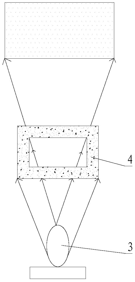
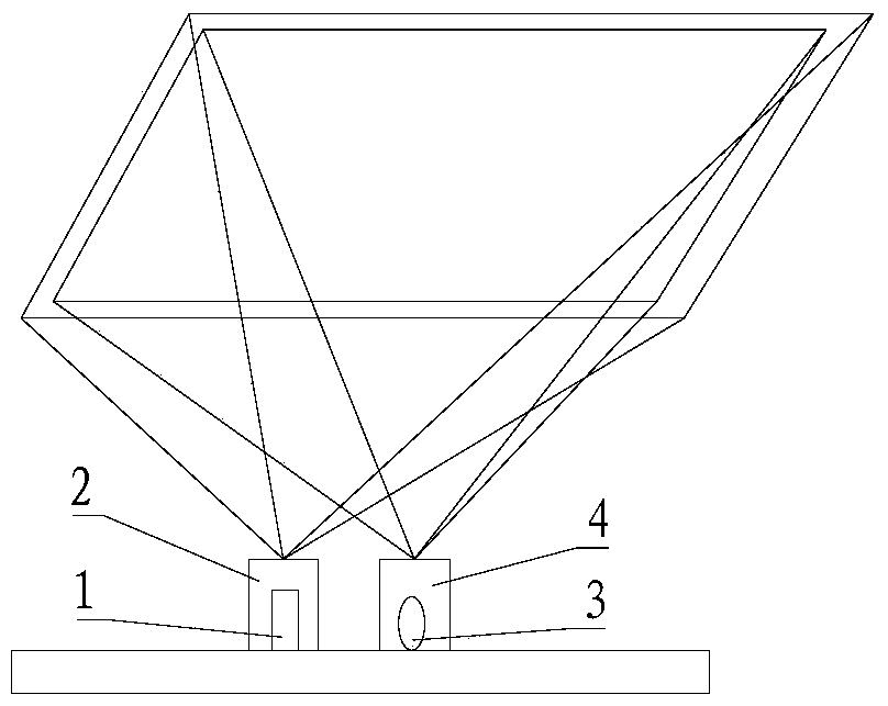
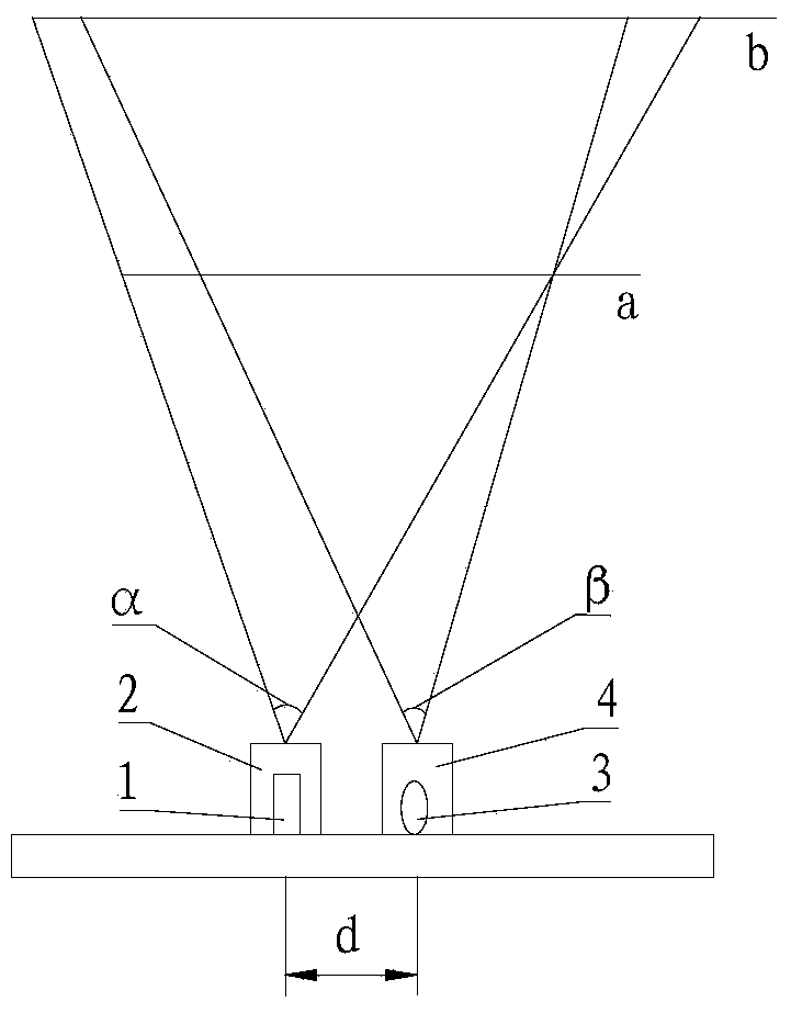
[0027] A two-dimensional code scanner that shares a supplementary light and an alignment light, including a camera 1, a light emitting diode 3, a lampshade 4, a camera cover 2, and a processor, the light emitting diode 3 is located in the lampshade 4, and the lampshade The top of 4 is provided with a rectangular through hole 5, the camera 1 is located in the camera cover 2, and the top of the camera cover 2 is provided with a rectangular through hole 5; the light emitting diode 3 is located at the side of the camera 1, the The illumination range of the light emitting diode 3 is within the shooting area of ​​the camera 1; the camera 1 and the light emitting diode 3 are connected to the processor.

[0028] Suppose the shooting angle of the camera 1 is α, the illumination angle of the LED 3 is β, the installation distance between the camera 1 and the LED 3 is d, and the starting horizontal...

Embodiment 2

[0029] Please refer to Figure 1 to Figure 4 , the second embodiment of the present invention is:

[0030] A two-dimensional code scanner sharing a supplementary light and an alignment light, comprising a camera 1, a light emitting diode 3, a lampshade 4, a camera cover 2, a light emitting diode dimming control circuit, and a processor, and the light emitting diode 3 is located in the In the lampshade 4, the top of the lampshade 4 is provided with a rectangular through hole 5, the camera 1 is located in the camera cover 2, and the top of the camera cover 2 is provided with a rectangular through hole 5; the light emitting diode 3 is located in the On the side of the camera 1, the illumination range of the light-emitting diode 3 is within the shooting area of ​​the camera 1; the light-emitting diode dimming control circuit is connected to the light-emitting diode 3, and the camera 1, the light-emitting diode dimming control circuit and the Processor connection.

[0031] In sum...


PUM


Abstract

A two-dimensional code scanner sharing a light supplementation lamp and an alignment lamp, comprising a camera, a light-emitting diode and a lampshade, wherein the light-emitting diode is located in the lampshade, and the top of the lampshade is provided with a rectangular through hole; and the light-emitting diode is located beside the camera, and the illumination range of the light-emitting diode is within a photographing region coverage of the camera. Light from the light-emitting diode not only can play a role of positioning for the photographing of a camera, but also can play a role of light supplementation.

Description

technical field [0001] The invention relates to the technical field of two-dimensional code scanners, in particular to a two-dimensional code scanner that shares a supplementary light and an alignment light. Background technique [0002] In the current QR code scanner, a supplementary light or an alignment light is installed on the side of the camera. The function of the supplementary light is that the camera has insufficient light when taking pictures, and the alignment light is used for quick alignment when scanning codes. It can improve the user's scanning experience. At present, there is no situation where the fill light and the alignment light are shared. [0003] The Chinese invention patent with the publication number CN103679113A discloses a method and system for positioning and focusing when an OTP device scans a two-dimensional code. A positioning light generating device for generating a positioning spot is provided in the OTP device, and the positioning light gen...

Claims


Application Information

Patent Timeline
Patent Type & Authority Patents(China)
IPC IPC(8): G06K7/10
CPCG06K7/10
Inventor 蒋锦扬叶芳耀
Owner FUJIAN LANDI COMML EQUIP CO LTD
Learn More