
Edge-lit type light-emitting diode (LED) backlight module and television

A backlight module and LED light source technology, applied in optics, light guides, light sources, etc., can solve problems such as uneven display brightness of liquid crystal panels, and achieve uniform light distribution and uniform display brightness

Active Publication Date: 2015-04-29
HISENSE VISUAL TECH CO LTD
View PDF6 Cites 0 Cited by
  • Summary
  • Abstract
  • Description
  • Claims
  • Application Information

AI Technical Summary

Problems solved by technology

[0018] Embodiments of the present invention provide a side-light LED backlight module and a TV set, which are used to solve the technical problem of uneven display brightness of liquid crystal panels in the prior art

Method used


Image

  • Edge-lit type light-emitting diode (LED) backlight module and television
  • Edge-lit type light-emitting diode (LED) backlight module and television
  • Edge-lit type light-emitting diode (LED) backlight module and television

Examples


Embodiment 1

[0056] Embodiment 1 of this application provides an edge-lit LED backlight module, please refer to Figure 4 and Figure 5 , the side-lit LED backlight module specifically includes:

[0057] Backplane 41;

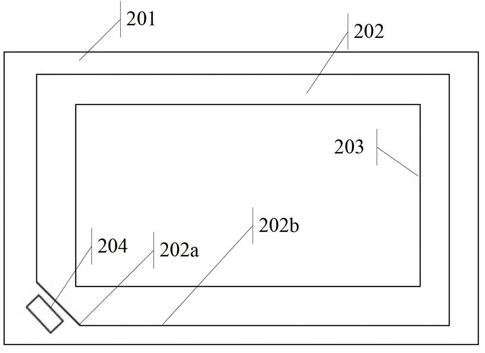
[0058] The light guide plate 42 is arranged on the surface of the back plate of the back plate 41, and the N corners 42a of the four corners of the light guide plate 42 are wedge-shaped, wherein, N is any integer from 1 to 4;

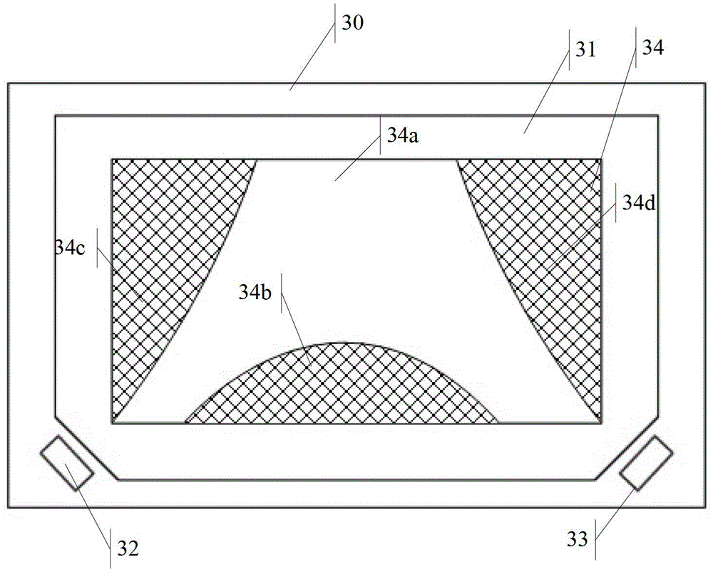
[0059] N groups of LED light sources 43, the i-th group of LED light sources in the N groups of LED light sources 43 are arranged corresponding to the i-th corner of the N corners 42a, and i is any integer from 1 to N; wherein, The incident light generated by the i-th group of LED light sources is incident on the light guide plate 42 from the i-th corner; the i-th group of LED light sources in the N groups of LED light sources 43 includes a first group of LED sub-light sources 51 and At least two groups of LED sub-light sources including the secon...

Embodiment 2

[0090] Based on the same inventive concept, Embodiment 2 of this application provides a TV set, please refer to Figure 11 , the TV specifically includes the following structure:

[0091] Chassis 111;

[0092] a processor 112, arranged in the casing 111;

[0093] The display unit 113 is arranged on the casing 111 and connected to the processor 112, wherein the display unit 113 includes any side-lit LED backlight module 113a described in Embodiment 1 of this application.


PUM


Abstract

The invention discloses an edge-lit type light-emitting diode (LED) backlight module and a television and achieves a technical effect that a liquid crystal display panel is more uniform in display luminance. The edge-lit type LED backlight module comprises a back plate, a light guiding plate, N sets of LED light sources and a liquid crystal display panel. The light guiding plate is arranged on the surface of the back plate and N corner portions of four corner portions of the light guiding plate are wedge-shaped. An i set of LED light sources and an i corner portion of the N corner portions are correspondingly arranged, and i is an arbitrary integer from 1 to N. Incident lights which are produced by the i set of LED light sources enter into the light guiding plate from the i corner. The liquid crystal display panel is arranged on the surface of the light guiding plate. The i set of LED light sources of the N sets of LED light sources comprises a first set of LED light sources and a second set of LED light sources which is connected with the first set of the LED light sources. A first incline angle is located between the first set of LED light sources and a first lateral edge of the light guiding plate. A second incline angle is located between the second set of LED light sources and the first lateral edge of the light guiding plate.

Description

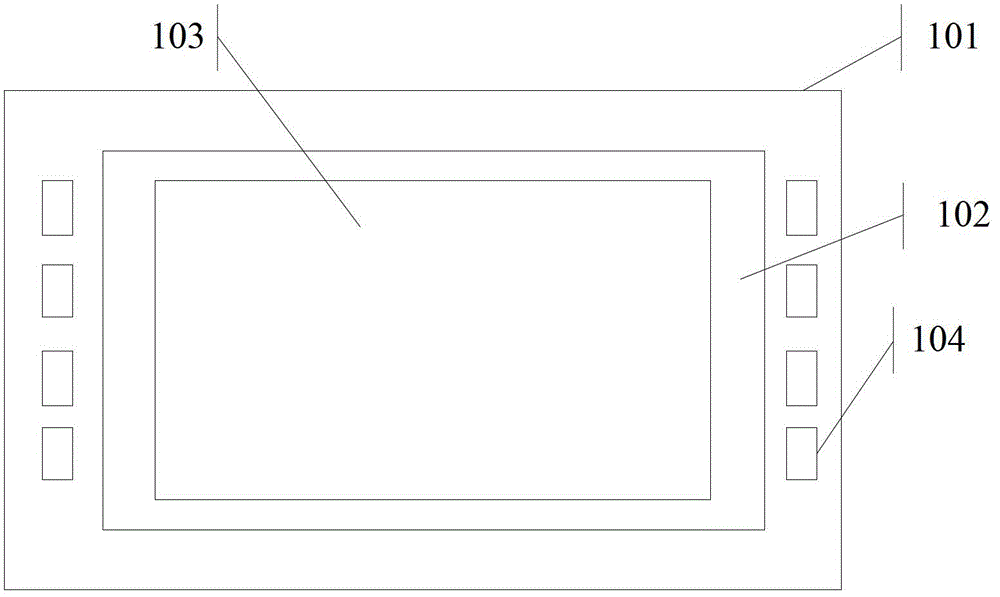
technical field [0001] The invention relates to the field of display technology, in particular to a side-light LED backlight module and a TV set. Background technique [0002] With the development of electronic technology, more and more electronic devices have been produced, among which, many electronic devices have liquid crystal display screens. Usually, liquid crystal display screens include liquid crystal panels and backlight modules. The liquid crystal panels are composed of two layers A liquid crystal layer is sandwiched between the glass backplane. Since the liquid crystal panel itself does not emit light, it needs to provide a uniform light source system through the backlight module. [0003] In the prior art, the LCD panel can be provided with a light source system through a direct-type backlight module or an edge-type backlight module. In this case, please refer to figure 1 , the side-type backlight module includes the following structure: [0004] Backplane 101;...

Claims


Application Information

Patent Timeline
Patent Type & Authority Patents(China)
IPC IPC(8): G02F1/13357F21V19/00F21V8/00F21Y101/02F21Y115/10
Inventor 邵坤黄奔翟玉帅
Owner HISENSE VISUAL TECH CO LTD
Learn More