AB dispenser adhesive outlet mixing valve

A mixing valve and dispensing machine technology, which is applied in the direction of valve details, valve device, valve housing structure, etc., can solve the problems of lower injection accuracy, deformation of valve channel and valve port, and inability to control the flow of glue well, to achieve The effects of improving spraying accuracy, reducing changes, saving glue and manual cleaning costs

Active Publication Date: 2015-10-28
苏州光宝科技股份有限公司
View PDF11 Cites 3 Cited by
  • Summary
  • Abstract
  • Description
  • Claims
  • Application Information

AI Technical Summary

Problems solved by technology

However, because the valve passage is a straight pipe, it is impossible to provide enough bearing surface for the glue to coordinate with the air pressure, so the mixing effect is not ideal.
[0005]3) It is known that the valve body is made of PP material. When the temperature of the glue is high, the valve body will expand with heat and contract with cold, resulting in More deformation, unable to control the glue flow well, greatly reducing the injection accuracy

Method used


Image

  • AB dispenser adhesive outlet mixing valve
  • AB dispenser adhesive outlet mixing valve
  • AB dispenser adhesive outlet mixing valve

Examples


Embodiment 1

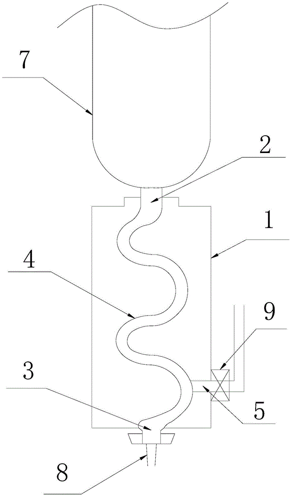
[0031] Embodiment 1: as figure 1 Shown is a specific embodiment of the AB glue dispenser glue mixing valve of the present invention, which has a valve body 1, an upper valve port 2 is opened on the top of the valve body 1, a lower valve port 3 is opened on the bottom of the valve body, and the valve body 1 There is a valve channel 4 connecting the upper and lower valve ports 2 and 3 inside, and the valve body 1 is also provided with an air inlet 5 connecting the valve channel 4 and the external air pump (not shown).

[0032] The core improvement of the present invention is that the valve channel 4 is designed with a bend, combined with figure 1 As shown, there are four bends on the valve passage 4 in this embodiment, and these bends are arc bends, but these bends are not bends with the same size and shape. In actual implementation, the specific number of bends can be determined as required, and each bend can give the glue a bearing surface against gravity.

[0033] T...

Embodiment 2

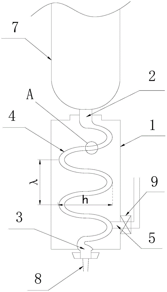
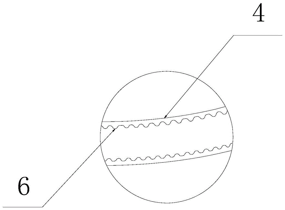
[0036] Embodiment 2: as figure 2 As shown, compared with Embodiment 1, the present invention differs in that the valve channel 4 is designed as a uniform sinusoidal waveform with five half-waves, and the ratio of the pitch λ to the amplitude h of the sinusoidal wave in this embodiment is 1 . Simultaneously combine image 3 As shown, the surface of the inner wall 6 of the valve channel 4 is a rough surface distributed with protrusions, specifically uniform and continuous corrugations, so as to improve the viscous force of the glue. The rest of this embodiment are the same as embodiment 1.

Embodiment 3

[0037] Embodiment 3: as Figure 4 As shown, the difference between the present invention and the embodiment 2 is that the valve channel 4 is designed as a uniform helical shape with nine threads, and the ratio of the pitch S to the major diameter D of the helix in this embodiment is 1. At the same time, the surface of the inner wall of the valve channel 4 in this embodiment is also designed with uniform and continuous corrugations, see image 3 shown. The rest of this embodiment are the same as embodiment 1.


PUM


Abstract

The invention discloses an AB dispenser adhesive outlet mixing valve which comprises a valve body and a valve channel, wherein the valve body is provided with an upper valve port and a lower valve port, and the valve channel is formed in the valve body and connected with the upper valve port and the lower valve port. The valve body is further provided with an air inlet connecting the valve channel and an external air pump. The AB dispenser adhesive outlet mixing valve is characterized in that the valve channel is provided with one or more bent parts. Compared with a conventional adhesive outlet valve with a straight valve channel, due to the fact that the bent parts are arranged in the valve channel, certain bearing faces are provided for adhesives to resist gravity, and therefore the adhesive leakage phenomenon under the non-pressurized condition can be effectively prevented, and the adhesives and labor cleaning cost are saved; the bent valve channel and strong pressure interact with each other, the adhesives can be well stirred, the mixing effect of the adhesives in the valve channel is greatly improved, and the quality of dispensed products is further improved.

Description

technical field [0001] The invention belongs to the technical field of improving the structure of a glue outlet valve of a glue dispenser, and in particular relates to a glue outlet mixing valve of an AB glue dispenser. Background technique [0002] AB dispensing machine, that is, two-liquid dispensing machine, compared with the general single-component glue dispensing machine, can adapt to the dispensing of two-component glue mixing ratio, and is currently a relatively mature dispensing equipment. In this type of dispensing machine, the glue valve is a key component. The valve port on the upper part of the valve body is used to connect the glue bucket, and the valve port on the lower part is connected to the dispensing needle. The internal valve channel and external air pump equipment are used to provide air pressure to extrude the glue, and at the same time, it is convenient to control the glue flow. However, the known glue outlet valve exposes the following problems in a...

Claims


Application Information

Patent Timeline
Patent Type & Authority Applications(China)
IPC IPC(8): F16K27/00
CPCF16K27/00
Inventor 郭勇夏志云井雪峰
Owner 苏州光宝科技股份有限公司
Why Eureka
Try Eureka