Separable hydraulic sliding sleeve for oil and gas wells

A hydraulic sliding sleeve and separation technology, which is used in wellbore/well components, wellbore/well valve devices, and production fluids, etc., can solve the problem of not being able to separate the tubing from the completion tool, and achieve simple structure and high performance. Reliable and easy-to-operate results

Active Publication Date: 2018-05-25
BC P INC CHINA NAT PETROLEUM CORP +1
View PDF8 Cites 0 Cited by
  • Summary
  • Abstract
  • Description
  • Claims
  • Application Information

AI Technical Summary

Problems solved by technology

[0004] However, the existing technology represented by the above-mentioned patent documents still cannot realize the separation of the oil tubing and the completion tool. Therefore, it is necessary to design a downhole device to realize the separation of the oil pipe and the completion tool, so that when the tool string cannot be taken out, through the device Complete separation of the tubing from the completion tool to remove the upper tubing

Method used


Image

  • Separable hydraulic sliding sleeve for oil and gas wells
  • Separable hydraulic sliding sleeve for oil and gas wells
  • Separable hydraulic sliding sleeve for oil and gas wells

Examples


Embodiment 1

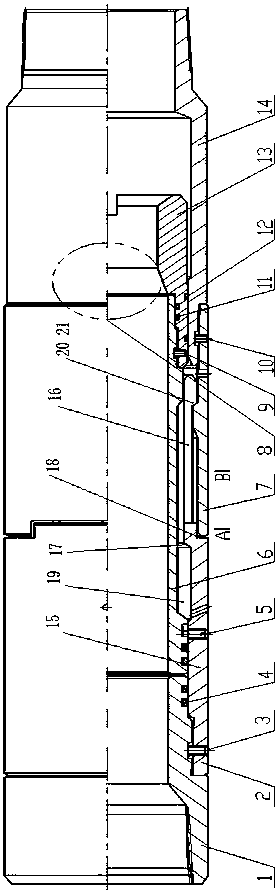
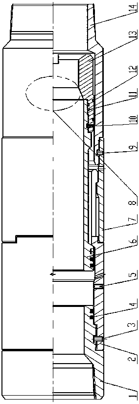
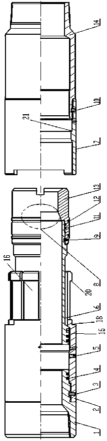
[0030] With reference to the drawings in the description, as the most basic embodiment of the present invention, it includes an upper joint 1, a lower joint 14, a ball seat 13, a throwing claw 2, an anti-rotation connecting cylinder 7 and a limit tube 6. The upper joint 1 It is fixedly connected with the throwing claw 2; the ball seat 13 and the limit tube 6 are fixedly connected to form a moving part, and is fixed in the inner cavity of the throwing claw 2 by a safety shear nail 5; the throwing claw 2 It includes a hollow cylindrical segment 15 and a claw segment 16 surrounded by a plurality of claw pieces. The hollow cylindrical segment 15 and the claw segment 16 are connected as one and formed with an upper step 17 and a lower step 18. The anti-rotation connection One end of the barrel 7 is fixedly connected to the lower joint 14, and the other end of the anti-rotation connecting barrel 7 is fastened to the lower step 18 formed between the hollow cylindrical section 15 and t...

Embodiment 2

[0033] On the basis of the above embodiments, the best implementation mode of the present invention is that the upper end of the claw slope 20 is inclined towards the end of the upper joint 1 . The upper joint 1 is fixedly connected with the throwing claw 2 by threads, and is fixed by set screws. The ball seat 13 is fixedly connected with the limit tube 6 through threads, and is fixed by set screws. The anti-rotation connecting cylinder 7 is fixedly connected with the lower joint 14 by threads, and fixed by set screws. Between the throwing claw 2 and the upper joint 1, between the throwing claw 2 and the limit tube 6, between the limit tube 6 and the ball seat 13, and between the ball seat 13 and the lower joint 14, there are At least one sealing ring. The other end of the anti-rotation connecting cylinder 7 is fastened to the lower step 18 formed between the hollow cylindrical section 15 and the claw segment 16 through the anti-rotation pin and the anti-rotation groove. Th...


PUM


Abstract

The invention discloses a separable type hydraumatic sliding sleeve for an oil gas well. The hydraumatic sliding sleeve comprises an upper joint, a lower joint, a ball seat, a releasing elastic claw, an anti-rotation connecting cylinder and a limiting tube, wherein the upper joint is fixedly connected with the releasing elastic claw; the ball seat and the limiting tube are fixedly connected to form a moving element; the moving element is fixed in the inner cavity of the releasing elastic claw through a safety shear pin; the releasing elastic claw comprises a hollow cylindrical section and an elastic claw piece section formed by encircling a plurality of elastic claw pieces; one end of the anti-rotation connecting cylinder is fixedly connected with the lower joint; the releasing elastic claw is positioned between the anti-rotation connecting cylinder and the limiting tube; a groove for accommodating the elastic claw piece section is formed in the outer wall of the limiting tube; an elastic claw oblique plane is arranged at the tail end of the releasing elastic claw; a step inner oblique plane matched with the elastic claw oblique plane is arranged on the inner wall of the anti-rotation connecting cylinder. Through the adoption of the separable type hydraumatic sliding sleeve, when a tool pipe column cannot be taken out after the production capacity-increasing revamp of the stratum, the separation of a feed-in oil tube and a completing tool is achieved through pressure building by ball throwing at the well opening, further the feed-in oil tube can be conveniently and quickly taken out, and the purpose of upper shaft operation is achieved.

Description

technical field [0001] The invention relates to a hydraulic sliding sleeve used for oil and gas wells, belonging to the technical field of downhole tools in the oil and gas industry. Background technique [0002] At present, the conventional production stimulation operation method of oil and gas wells is to connect the completion tools with the tubing and run them into the oil and gas wells to complete the acidification or fracturing of the formation to achieve the purpose of production stimulation. When the tool string in the well needs to be taken out after formation stimulation or oil and gas recovery, due to the influence of complex downhole conditions, the tool string cannot be taken out, which will affect the secondary operation of the wellbore. [0003] For example, the publication number is CN104481491A, and the publication date is April 1, 2015. The Chinese patent document discloses a loop control type casing sliding sleeve closing tool, including a body, a hydrauli...

Claims


Application Information

Patent Timeline
Patent Type & Authority Patents(China)
IPC IPC(8): E21B34/14E21B43/26E21B43/27
Inventor 黄煜鹏邹祥富肖勇王庆刘珂兵刘勇潘治强史耀伟黄奕
Owner BC P INC CHINA NAT PETROLEUM CORP
Why Eureka
Try Eureka