
Transmission device of full-automatic piston ring molding machine

A transmission device and piston ring technology, which is applied to the driving device of metal rolling mills, metal processing equipment, metal rolling, etc., can solve the problems of low production efficiency, loud noise, and easy wear and tear

Inactive Publication Date: 2015-10-28
安徽金斗机械制造有限责任公司
View PDF0 Cites 2 Cited by
  • Summary
  • Abstract
  • Description
  • Claims
  • Application Information

AI Technical Summary

Problems solved by technology

[0002] At present, the transmission mechanism of the piston ring rolling machine used by domestic piston ring manufacturing enterprises mostly adopts gear or chain transmission, the mechanical structure is complicated, the noise is large during transmission, easy to wear, and the safety is poor. It is difficult to achieve consistency, which not only affects the processing quality of piston rings, but also reduces production efficiency, and the manufacturing cost is high, which is inconvenient for maintenance and adjustment

Method used


Image

  • Transmission device of full-automatic piston ring molding machine
  • Transmission device of full-automatic piston ring molding machine

Examples


Embodiment Construction

[0008] The transmission device of a fully automatic piston ring molding machine of the present invention will be described in further detail below in conjunction with the accompanying drawings.

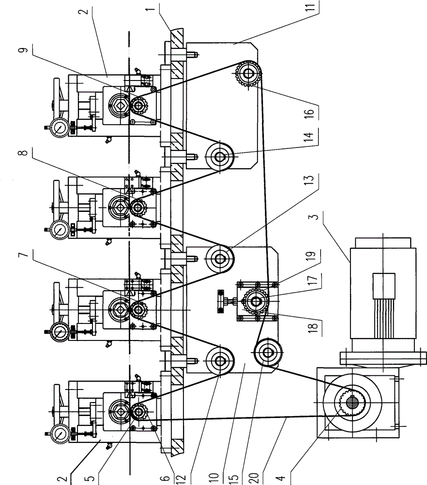
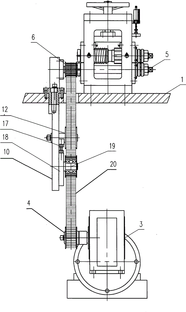
[0009] Depend on figure 1 , figure 2 It can be seen that the transmission device of a fully automatic piston ring forming machine in this embodiment is composed of a base panel 1, a main shaft base plate 2 fixedly installed above the base panel 1, a servo motor 3, an active toothed synchronous pulley 4, and The main shaft 5 fixed on the main shaft bottom plate 2, the first toothed main shaft synchronous pulley 6, the second toothed main shaft synchronous pulley 7, the third toothed main shaft synchronous pulley 8 and the fourth toothed main shaft synchronous pulley respectively installed on the main shaft 5 Toothed main shaft synchronous pulley 9, left idler bottom plate 10 and right idler bottom plate 11 fixed under machine base panel 1, first flat idler 12, second flat idler 13, t...


PUM


Abstract

The invention discloses a transmission device of a full-automatic piston ring molding machine. The transmission device is composed of a machine base panel, a main shaft base plate, a servo motor, a driving tooth-shaped synchronous belt wheel, main shafts, a first tooth-shaped main shaft synchronous belt wheel, a second tooth-shaped main shaft synchronous belt wheel, a third tooth-shaped main shaft synchronous belt wheel, a fourth tooth-shaped main shaft synchronous belt wheel, a left idler wheel base plate, a right idler wheel base plate, a first flat idler wheel, a second flat idler wheel, a third flat idler wheel, a fourth flat idler wheel, a tooth-shaped idler wheel and a gear tensioning adjusting device; the first tooth-shaped main shaft synchronous belt wheel, the second tooth-shaped main shaft synchronous belt wheel, the third tooth-shaped main shaft synchronous belt wheel and the fourth tooth-shaped main shaft synchronous belt wheel are installed on the respective main shafts respectively; and the left idler wheel base plate and the right idler wheel base plate are fixed below the machine base panel. The four flat idler wheels and the gear idler wheel are installed at the different positions, it is guaranteed that the tooth-shaped main shaft synchronous belt wheels on the four main shafts and precise rolling dies on the main shafts synchronously rotate in the same direction, the structure is simple and compact, the noise is small during transmission, the safety is good, adjustment is convenient, the requirement needed by the piston ring working procedure is met, the product quality is guaranteed, and the manufacturing cost is lower.

Description

(1) Technical field: [0001] The invention belongs to the field of mechanical equipment, and in particular relates to a transmission device of a fully automatic piston ring forming machine. (two) background technology: [0002] At present, the transmission mechanism of the piston ring rolling machine used by domestic piston ring manufacturing enterprises mostly adopts gear or chain transmission, the mechanical structure is complicated, the noise is large during transmission, easy to wear, and the safety is poor. It is difficult to achieve a consensus, which not only affects the processing quality of the piston ring, but also reduces the production efficiency, and the manufacturing cost is relatively high, which is inconvenient for maintenance and adjustment. (3) Contents of the invention: [0003] The purpose of the present invention is to provide a transmission device for a fully automatic piston ring forming machine. The device has a simple and compact structure, low nois...

Claims


Application Information

Patent Timeline
IPC IPC(8): B21B35/00
Inventor 程明根
Owner 安徽金斗机械制造有限责任公司
Learn More