
CT image metal artifact correction method

A technology for CT images and metal artifacts, applied in image enhancement, image analysis, image data processing, etc., can solve the problems of missing high-contrast substances on metal edges, uneven boundaries, and failure to feedback bone structure information

Active Publication Date: 2015-10-21
SUZHOU INST OF BIOMEDICAL ENG & TECH CHINESE ACADEMY OF SCI
View PDF7 Cites 26 Cited by
  • Summary
  • Abstract
  • Description
  • Claims
  • Application Information

AI Technical Summary

Problems solved by technology

However, if there are high-contrast structures around the metal area, such as bones, teeth, etc., the correction results will lose the structural information of the high-contrast material around the metal edge, which is precisely what clinicians are most concerned about.
The root cause is that the above interpolation method has unsmooth boundaries and fails to feed back the bone structure information of the metal edge into the corrected projection data

Method used


Image

  • CT image metal artifact correction method
  • CT image metal artifact correction method
  • CT image metal artifact correction method

Examples


Embodiment Construction

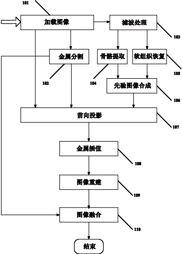
[0048] The technical implementation process of the present invention will be further described below in conjunction with the accompanying drawings and embodiments. figure 1 It is a schematic diagram of the execution flow of the method of the present invention.

[0049] The functions of each unit module are as follows:

[0050] The image loading unit 101 loads the CT image to be processed on the computer;

[0051] A metal segmentation unit 102, configured to segment the metal region in the CT image to construct a metal image;

[0052] Filtering unit 103, for suppressing the noise of CT image;

[0053] A bone extraction unit 104, configured to extract bone structure information around the metal area;

[0054] A soft tissue restoration unit 105, configured to restore the soft tissue information of the artifact area around the metal area;

[0055] A priori image synthesis unit 106, configured to synthesize a priori image;

[0056] Forward projection unit 107, used to generat...


PUM


Abstract

The invention provides a metal artifact correction method, comprising: first, employing a method based on a Markov random field model to divide metal areas, thereby solving the problem of inaccurate division of metal areas by a traditional metal artifact removal algorithm, and avoiding more secondary artifacts caused by inaccurate positioning of metal projection borders; and employing a prior interpolation algorithm to solve the problem of unsmooth borders of metal projection areas after linear interpolation; in addition, metal edge framework structure information is fed back to corrected projection data, thereby solving the problem that metal edge high contrast substance structures may be lost in correction results by a traditional interpolation algorithm.

Description

technical field [0001] The invention mainly aims at correcting metal artifacts in digital images and improving image quality, and mainly relates to digital image processing technology, in particular to image segmentation, filtering, interpolation and fusion technologies based on edge protection. Background technique [0002] In CT scanning imaging, the metal implants in the patient's body, such as joint prostheses, dental fillings, and spinal fixation bolts, have high attenuation to X-rays, resulting in very large noise in the data received by the detector. Radial bright streaks appear in CT images, while dark areas can occur around larger metallic areas or between multiple metallic areas. The existence of these metal artifacts directly reduces the quality of CT images and the accuracy of CT clinical diagnosis. [0003] At present, the mainstream metal artifact removal algorithm is a data synthesis method based on interpolation. For data affected by metal objects, an app...

Claims


Application Information

Patent Timeline
IPC IPC(8): G06T5/00G06T7/00A61B6/03
Inventor 李铭郑健徐品刘敏袁刚
Owner SUZHOU INST OF BIOMEDICAL ENG & TECH CHINESE ACADEMY OF SCI
Learn More