Bridge telescopic beam structure and installation method thereof

A technology of telescopic beams and bridges, applied in bridges, bridge parts, bridge construction, etc., to achieve life-long maintenance-free, prolong service life, and reduce damage

Inactive Publication Date: 2016-09-07
冯明硕 +9
View PDF8 Cites 0 Cited by
  • Summary
  • Abstract
  • Description
  • Claims
  • Application Information

AI Technical Summary

Problems solved by technology

However, the telescopic device of this structure does not change the basic design principle of the traditional telescopic device, and only improves the use and structure of some parts, which cannot fundamentally solve the problem that the telescopic device needs to be disassembled and maintained regularly and the vehicle is running. bumpy phenomenon

Method used


Image

  • Bridge telescopic beam structure and installation method thereof
  • Bridge telescopic beam structure and installation method thereof

Examples


Embodiment Construction

[0021] The standard parts used in the present invention can be purchased from the market, and the special-shaped parts can be customized according to the instructions and the accompanying drawings. The specific connection methods of each part adopt mature bolts, rivets, welding in the prior art , pasting and other conventional means, no longer described in detail here.

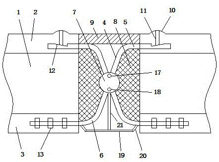
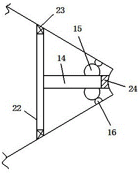
[0022] refer to Figure 1-2 , a specific embodiment of the present invention is: a rubber layer 2 is arranged on the top of the two end faces 1 of the bridge, a steel plate layer 3 is arranged on the bottom of the end faces, a buffer device is arranged between the two end faces 1, and the buffer device includes two hinged joints. The buffer rod includes a first straight part 4 in the middle and a second straight part 5 at both ends. The first straight part 4 and the second straight part 5 are connected by a bending part 6. The buffer rod The hinged part is set on the first straight line part 4, the outer side...


PUM


Abstract

The invention discloses a bridge telescopic beam structure. The top portion of each of the two end surfaces is provided with a rubber layer, and the bottom portion of each end surface is provided with a steel plate layer. A buffer device is arranged between the two end surfaces. The buffer device comprises two buffer rods which are hinged to each other. Each buffer rod comprises a first linear portion at the middle part and second linear portions at the two ends; the first liner portion is connected to the second linear portions through bent portions; the hinging position is located on the first linear portion of the buffer rod; a flexible housing is arranged on the outer side of the hinging position of the buffer rod; and the space between the buffer rod and the corresponding end surface is filled with a buffer layer. A connecting layer is arranged between the rubber layers on the two end surfaces. The invention also provides an installation method for the bridge telescopic beam structure. According to the invention, shortcomings in the prior art can be overcome, the maintenance operation of the telescopic beam is simplified, and the driving stationarity of a vehicle is improved.

Description

technical field [0001] The invention relates to the technical field of bridge construction, in particular to a bridge telescopic beam structure and an installation method thereof. Background technique [0002] The telescopic beam of the bridge is one of the places where the whole bridge bears the largest load, which ensures that the bridge does not undergo rigid deformation when it receives external forces or changes in the environment. Due to the particularity of the telescopic beam, its service life is relatively short among the entire bridge components. Chinese invention patent CN102102340B discloses a bridge expansion device and its installation method. Compared with the traditional moller seam technology, the later service life and maintenance cost have been significantly improved. However, the telescopic device of this structure does not change the basic design principle of the traditional telescopic device, and only improves the use and structure of some parts, which...

Claims


Application Information

Patent Timeline
Patent Type & Authority Patents(China)
IPC IPC(8): E01D19/06
Inventor 冯明硕唐乃浩何华海张明王永顺刘芳芳吴娅君王辉张灿路陈光
Owner 冯明硕
Why Eureka
Try Eureka