Pneumatic tuck-in device for loom

A tuck-in device and loom technology, applied in looms, textiles, textiles and papermaking, etc., can solve the difficulty of adjusting and controlling the tuck-in width, difficult to fine-tune the flying attitude of the yarn, and reduce the dyeing of finished fabrics. It can improve the efficiency of adjustment work, reduce the risk of airway blockage, and improve the dye permeability.

Active Publication Date: 2017-05-03
SHANDONG RIFA TEXTILE MACHINERY
View PDF9 Cites 0 Cited by
  • Summary
  • Abstract
  • Description
  • Claims
  • Application Information

AI Technical Summary

Problems solved by technology

[0003] 1. The fold-in hole is divided into two directions of airflow: backward fold-in and inward fold-in. Since there is only one air intake hole, the pressure can only be adjusted together. It is difficult to fine-tune the flight attitude when the yarn is folded in, so that The difficulty of adjusting and controlling the folded-in edge width increases;
[0004] 2. In the prior art, there are usually two methods of sealing the process hole of the folded block: rivet sealing and glue sealing. Among them, the rivet sealing has the hidden danger of air leakage, and the glue sealing has the possibility of blocking the airway and long-term use. Hidden dangers such as aging and degumming;
[0005] 3. The tuck-in block size of the prior art is relatively thick, and it is difficult to control the tuck-in length within 8mm when making some special fabrics, which reduces the dyeing and penetration of the finished fabric and increases the printing and dyeing cost

Method used


Image

  • Pneumatic tuck-in device for loom
  • Pneumatic tuck-in device for loom
  • Pneumatic tuck-in device for loom

Examples


Embodiment Construction

[0025] In order to better understand the present invention, the implementation manner of the present invention will be explained in detail below in conjunction with the accompanying drawings.

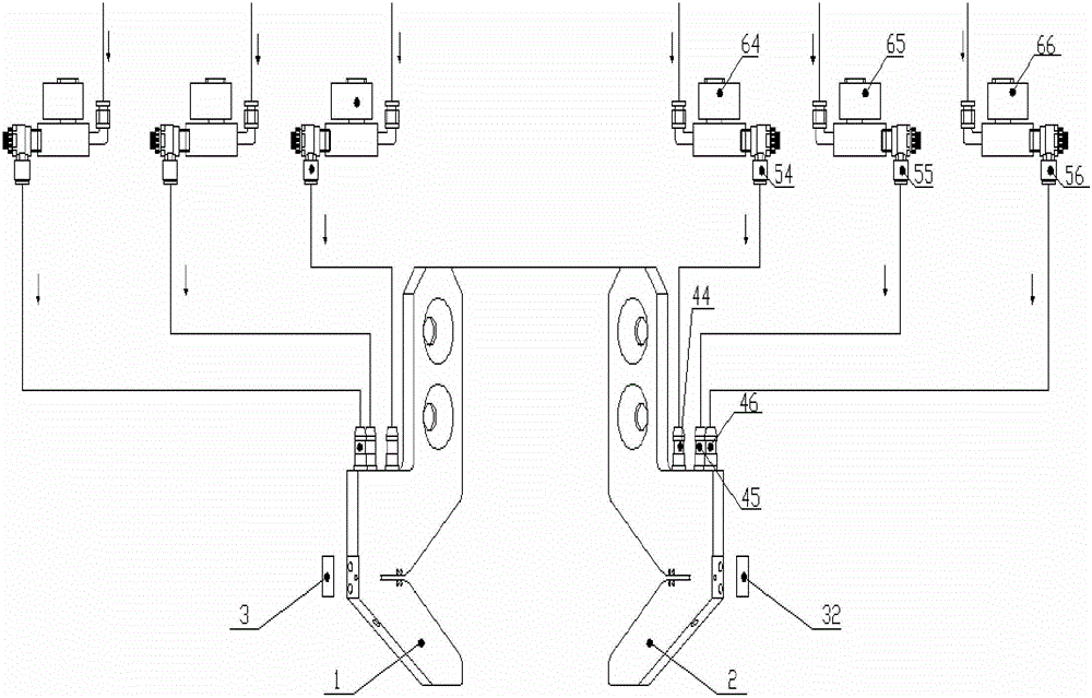
[0026] Such as Figure 1 to Figure 8 As shown, a pneumatic folding device for a loom includes a left folding block 1 and a right folding block 2, and cover plates 3, 32 and copper joints 44, 45 are respectively provided on the left folding block 1 and the right folding block 2. , 46, shut-off valves 54, 55, 56, solenoid valves 64, 65, 66, the left folding block 1 and the right folding block 2 are symmetrical structures, wherein the left folding block 1 is installed on the left side of the cloth, and the right folding block 2 installed on the right side of the cloth. The structure will be described in detail below with respect to the structure of the fold-in block 2 on the right side.

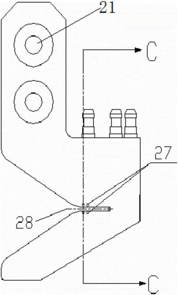
[0027] Such as Figure 1-Figure 5 As shown, two installation holes 21 are provided on the upper par...


PUM


Abstract

The invention discloses a pneumatic fold selvage device used for a weaving machine. The device comprises a left folding block and a right folding block. The left folding block is installed on the left side of a cloth, and a right folding block is installed on the right side of the cloth. The upper parts of the left folding block and the right folding block are provided with installing holes. The middle parts of the left folding block and the right folding block are provided with holding holes. The holding holes are connected with a first high-pressure air channel. The outer side of the holding hole is provided with a first folding hole and a second folding hole in sequence. The first folding hole is connected with a second high-pressure air channel. The second folding hole is connected with a third high-pressure air channel. Both of the left folding block and the right folding block are provided with a first technical hole and a second technical hole on the outer sides of the lower parts. The first technical hole is communicated with the second folding hole. The second technical hole is communicated with the first folding hole. The outer end faces of the first technical hole and the second technical hole are sealed. The inner side of the lower part of the folding block is provided with nozzle holes. The nozzle holes are communicated with the second technical hole. The air outlets of the nozzle holes are cooperated with a side of the cloth. The device realizes refined adjustment of flight attitude when yarns are folded, and control adjustability of fold selvage width is improved.

Description

technical field [0001] The invention relates to the technical field of loom equipment, in particular to a pneumatic hemming device for a loom. Background technique [0002] Air-jet looms in the prior art need to adopt pneumatic hemming when weaving smooth-edged fabrics. During pneumatic hemming, the folding-in block is used to perform the folding-in operation by using the folding-in airflow and the holding airflow. The problems with this structure and approach are: [0003] 1. The fold-in hole is divided into two directions of airflow: backward fold-in and inward fold-in. Since there is only one air intake hole, the pressure can only be adjusted together. It is difficult to fine-tune the flight attitude when the yarn is folded in, so that The difficulty of adjusting and controlling the width of fold-in side increases; [0004] 2. In the prior art, there are usually two methods of sealing the process hole of the folded block: rivet sealing and glue sealing. Among them, the ...

Claims


Application Information

Patent Timeline
Patent Type & Authority Patents(China)
IPC IPC(8): D03D47/48
Inventor 王涛吉学齐张玉杰王共超
Owner SHANDONG RIFA TEXTILE MACHINERY
Why Eureka
Try Eureka