Mini-tiller worm-gear case assembly device

A worm gear box and micro-tiller technology, which is applied in the fields of tillage equipment, transmission parts, mechanical equipment, etc., can solve the problems of decreased farmland efficiency, short stay time, and insufficient effect, and achieve the effect of improving practicability.

Inactive Publication Date: 2015-10-21
GAOYOU NORTH POWER MACHINERY
View PDF6 Cites 0 Cited by
  • Summary
  • Abstract
  • Description
  • Claims
  • Application Information

AI Technical Summary

Problems solved by technology

In terms of transmission mode, most micro tillage machines use single worm gear transmission, that is, a worm and a worm gear are connected to each other for transmission. In this case, the time for the tiller to stay in the same field is too short, resulting in a poor effect after one-time plowing, and it is often necessary to repeatedly plow the field back and forth. Many times, the efficiency of cultivated land will decrease

Method used


Image

  • Mini-tiller worm-gear case assembly device
  • Mini-tiller worm-gear case assembly device
  • Mini-tiller worm-gear case assembly device

Examples


Embodiment 1

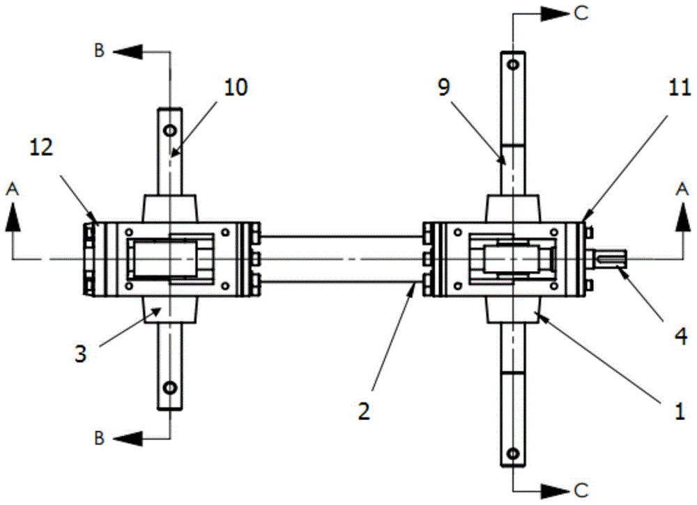
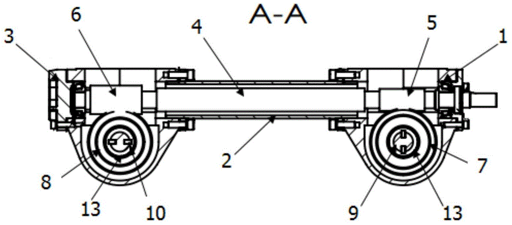
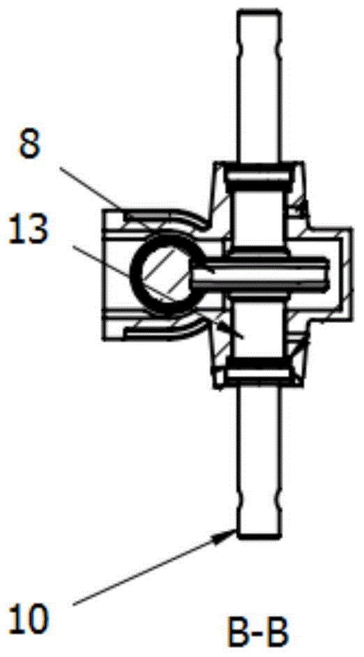
[0017] Such as Figure 1-Figure 4 As shown in the worm gear box assembly device of a micro tillage machine, the ends of the front worm gear box 1 and the rear worm gear box 3 are connected by bolts fixed by hexagon socket head screws, and the front worm gear box 1 of the front end cover and the rear end cover are connected through the worm gear box The pipe 2 is connected with the rear worm gear 3 box, the front worm gear box 1, the rear worm gear box 3 and the worm gear box connecting pipe 2 are all connected by bolts fixed by socket head cap screws, the middle part of the worm 4 is located in the worm gear connecting pipe 2, and the front part of the worm 4 , and the rear part are the front worm teeth 5 and the rear worm teeth 6 respectively. The helical direction of the tooth 6 is left-handed, the front worm gear 5 and the rear worm gear 6 are respectively connected to the front worm gear 7 and the rear worm gear 8, the helical direction of the worm gear teeth of the front ...

Embodiment 2

[0019] Such as Figure 1-Figure 4 As shown in the worm gear box assembly device of a micro tillage machine, the ends of the front worm gear box 1 and the rear worm gear box 3 are connected by bolts fixed by hexagon socket head screws, and the front worm gear box 1 of the front end cover and the rear end cover are connected through the worm gear box The pipe 2 is connected with the rear worm gear 3 box, the front worm gear box 1, the rear worm gear box 3 and the worm gear box connecting pipe 2 are all connected by bolts fixed by socket head cap screws, the middle part of the worm 4 is located in the worm gear connecting pipe 2, and the front part of the worm 4 , and the rear part are the front worm teeth 5 and the rear worm teeth 6 respectively. The helical direction of the tooth 6 is left-handed, the front worm gear 5 and the rear worm gear 6 are respectively connected to the front worm gear 7 and the rear worm gear 8, the helical direction of the worm gear teeth of the front ...

Embodiment 3

[0021] Such as Figure 1-Figure 4 As shown in the worm gear box assembly device of a micro tillage machine, the ends of the front worm gear box 1 and the rear worm gear box 3 are connected by bolts fixed by hexagon socket head screws, and the front worm gear box 1 of the front end cover and the rear end cover are connected through the worm gear box The pipe 2 is connected with the rear worm gear 3 box, the front worm gear box 1, the rear worm gear box 3 and the worm gear box connecting pipe 2 are all connected by bolts fixed by socket head cap screws, the middle part of the worm 4 is located in the worm gear connecting pipe 2, and the front part of the worm 4 , the rear part are respectively the front worm gear 5 and the rear worm gear 6, the front worm gear 5 and the rear worm gear 6 are located in the front worm gear box 1 and the rear worm gear box 3 respectively, the helical direction of the front worm gear 5 is left-handed, and the rear worm gear The helical direction of ...


PUM


Abstract

The invention relates to a mini-tiller worm-gear case assembly device, and belongs to the field of agricultural machinery. In the mini-tiller worm-gear case assembly device, a front worm-gear case is connected with a rear worm-gear case through a worm-gear case connecting pipe, the central part of a worm is arranged in the worm-gear case connecting pipe, the front part of the worm is provided with a front worm tooth, the rear part of the worm is provided with a rear worm tooth, the front worm tooth is arranged in the front worm-gear case, the rear worm tooth is arranged in the rear worm-gear case, the spiral direction of the front worm tooth is opposite to that of the rear worm tooth, the front worm tooth is connected with a front worm gear, the rear worm tooth is connected with a rear worm gear, the center of the front worm gear is connected with a wheel axle and the center of the rear worm gear is connected with a tilling blade shaft, or the center of the front worm gear is connected with tilling blade shaft and the center of the rear worm gear is connected with the wheel axle. The mini-tiller worm-gear case assembly device has practical functions, the transmission mode is configured in way that one worm and two worm gears are used for transmission, the rotating direction of the tilling blade is opposite to that of the vehicle wheels, and therefore when the mini tiller works, the duration of stay of the tilling blade on the same cultivated land is prolonged, after one-time tillage, the land cultivated by the mini tiller is more mature and finer than the land cultivated by a conventional mini tiller, and the tilling efficiency is greatly improved, and the practicality of the mini tiller is greatly is improved.

Description

technical field [0001] The invention belongs to the field of agricultural machinery, in particular to a worm gear box assembly device for a tiller. Background technique [0002] As a commonly used agricultural machine, the tiller is more and more widely used in China's agricultural production, and plays an increasingly important role in plowing and farming. In terms of transmission mode, most micro tillage machines use single worm gear transmission, that is, a worm and a worm gear are connected to each other for transmission. In this case, the time for the tiller to stay in the same field is too short, resulting in a poor effect after one-time plowing, and it is often necessary to repeatedly plow the field back and forth. Many times, the efficiency of cultivated land will decrease. Contents of the invention [0003] The purpose of the present invention is to overcome above-mentioned deficiency, provide a kind of tillage machine worm gear box assembly device, under the ef...

Claims


Application Information

Patent Timeline
Patent Type & Authority Applications(China)
IPC IPC(8): A01B33/08F16H57/039F16H57/023
Inventor 柏远康常胜安张正
Owner GAOYOU NORTH POWER MACHINERY
Why Eureka
Try Eureka