
High-power trigger booster system based on surging current limitation

A technology of surge current and boost system, applied in control/regulation system, conversion of DC power input to DC power output, conversion of AC power input to DC power output, etc., to achieve cost savings, low power loss, and high stability sexual effect

Inactive Publication Date: 2015-10-14
CHENGDU JIESHENG TECH CO LTD
View PDF0 Cites 2 Cited by
  • Summary
  • Abstract
  • Description
  • Claims
  • Application Information

AI Technical Summary

Problems solved by technology

[0003] The purpose of the present invention is to overcome the defect that the traditional trigger boost circuit cannot meet the needs of some high-power production equipment, and to provide a high-power trigger boost system based on inrush current limitation that can output higher power stably

Method used


Image

  • High-power trigger booster system based on surging current limitation
  • High-power trigger booster system based on surging current limitation

Examples


Embodiment

[0021] Such as figure 1 As shown, the present invention mainly consists of a rectification and filtering circuit, a trigger circuit connected to the rectification and filtering circuit, a boost circuit connected to the trigger circuit, and a two-stage low-pass filter amplifier circuit connected to the boost circuit. It consists of a linear drive circuit between the circuit and the trigger circuit, and a surge current limiting circuit connected in series between the rectifier circuit and the two-stage low-pass filter amplifier circuit.

[0022] The structure of the inrush current limiting circuit is as figure 1 As shown, that is, it is composed of PDP type Linton tube Q3, PDP type Linton tube Q4, triode VT9, inductor L, resistor R22, resistor R23, resistor R24, resistor R25, resistor R26, resistor R27, thermistor R28, Resistor R29, resistor R30, resistor R31, polar capacitor C17, polar capacitor C18, polar capacitor C19, polar capacitor C20, polar capacitor C21, Zener diode D5...


PUM


Abstract

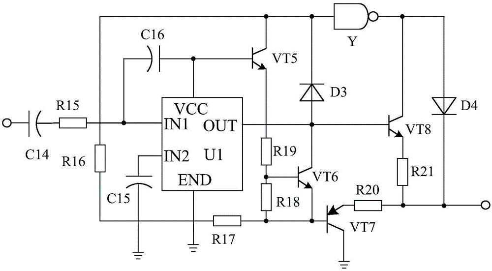
The invention discloses a high-power triggering and boosting circuit based on linear driving. The high-power triggering and boosting circuit based on linear driving is mainly composed of a rectification filter circuit, a triggering circuit connected with the rectification filter circuit, a boosting circuit connected with the triggering circuit, a two-stage low-pass filtration and amplification circuit connected with the boosting circuit. The high-power triggering and boosting circuit based on linear driving is characterized in that a linear driving circuit is arranged between the filter circuit and the triggering circuit and is composed of a driving chip U1, a triode VT5, a triode VT6, a triode VT7, a triode VT8, a capacitor C14, a resistor R16 and the like, the positive electrode of capacitor C14 is connected with the filter circuit, the negative electrode of the capacitor C14 passes through a resistor R15 and then is connected with an IN1 pin of the driving chip U1, one end of the resistor R16 is connected with the collector electrode of the triode VT5, and the other end of the resistor R16 passes through a resistor R17 and then is connected with the base electrode of the triode VT7. According to the high-power triggering and boosting circuit based on linear driving, the linear driving circuit is adopted, in this way, higher power can be output by the circuit, high stability can be maintained, and the operating requirement of high-power production equipment is met.

Description

technical field [0001] The invention relates to a boost circuit, in particular to a high-power trigger boost system based on surge current limitation. Background technique [0002] With the continuous improvement of people's living standards and the performance of electrical products, people's requirements for trigger boost circuits are also getting higher and higher. In production, people pay more and more attention to production efficiency, and many production processes use mechanization. However, due to the low design level of the traditional trigger boost circuit, it cannot meet the requirements of some high-power production equipment, thus affecting the production efficiency. How to enable the circuit to output more power stably is an urgent need to be solved. Contents of the invention [0003] The purpose of the present invention is to overcome the defect that the traditional trigger boost circuit cannot meet the needs of some high-power production equipment, and t...

Claims


Application Information

Patent Timeline
Patent Type & Authority Applications(China)
IPC IPC(8): H02M7/217H02M3/335H02M1/32
CPCH02M3/33569
Inventor 雷明方
Owner CHENGDU JIESHENG TECH CO LTD
Learn More