
LED display module group, and base frame disc and optical control circuit board both for same

A display module and base frame technology, applied in the direction of circuit layout, light source, point light source, etc., can solve the problems of heavy workload, impossibility of installation, bulky and large structure, etc., and achieve strong wind load bearing capacity, Easy installation and removal, low investment cost

Active Publication Date: 2015-10-14
深圳市熠鸿光电科技有限公司
View PDF6 Cites 10 Cited by
  • Summary
  • Abstract
  • Description
  • Claims
  • Application Information

AI Technical Summary

Problems solved by technology

[0005] 2) Grille type: The above-mentioned box-type LED display module itself is relatively bulky and opaque. The LED display screen assembled and installed by it is a huge whole board, which is heavy and airtight. Therefore, there is a kind of Grid-style LED display module
Although these two LED display modules have a certain degree of transparency, they cannot get rid of the shackles that the module itself is a rigid body that cannot be bent arbitrarily. The installation is realized, and the installation and fixing method has a large amount of engineering
[0018] Through the above analysis of the LED display screen, we found that whether the LED screen module is a box-type airtight type, or a grid-like, grid-like permeability, they are all rigid bodies that cannot be bent under the action of external forces. , once it is bent by external force, the structure and circuit will be damaged, and the structures used to assemble them are all bulky and require high precision.
The method of directly installing LED modules as pixels is either a huge workload, or it is pre-assembled into a module unit and becomes bulky and impermeable. At the same time, the electrical performance and brightness of this circuit mode are not ideal.

Method used


Image

  • LED display module group, and base frame disc and optical control circuit board both for same
  • LED display module group, and base frame disc and optical control circuit board both for same
  • LED display module group, and base frame disc and optical control circuit board both for same

Examples


Embodiment Construction

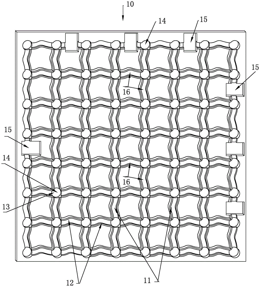
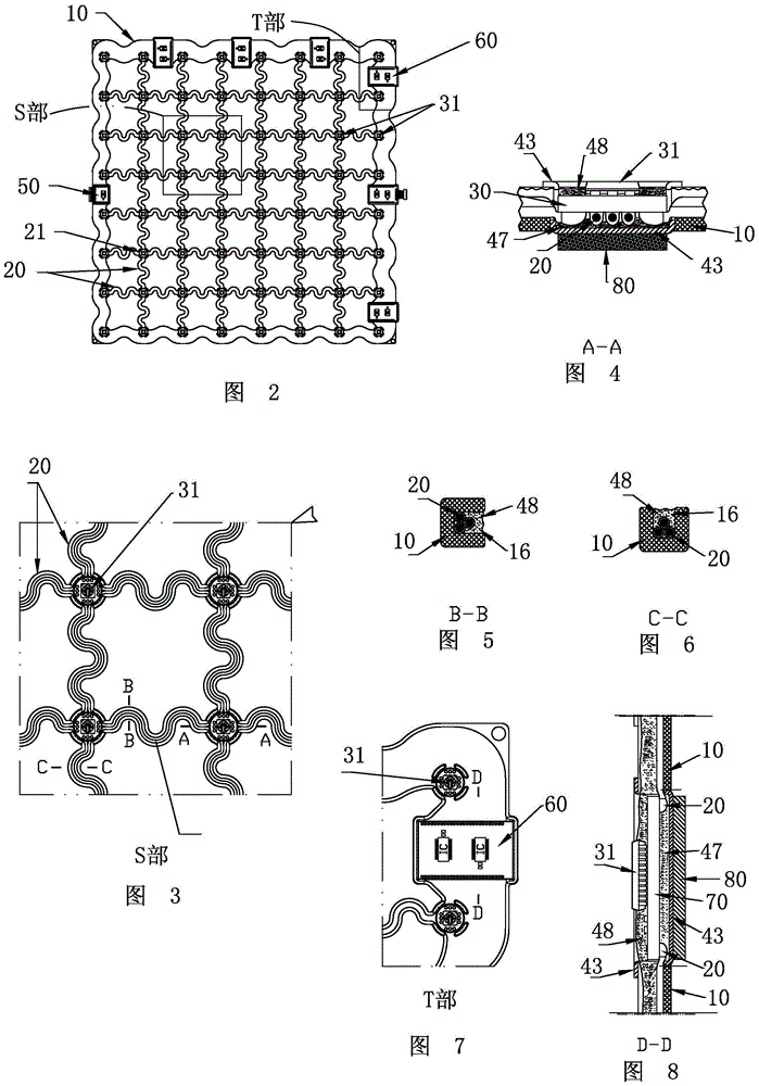
[0065] Such as figure 2 - Shown in 10: the LED display module of the present invention is made of soft plastic in the form of a checkerboard grid (see figure 1 ) pedestal plate 10 and the LED light control circuit board assembled on the pedestal plate 10 and the protective assembly 40 that can protect the electronic components on the LED light control circuit board from being waterproof, dustproof, impact resistant and anti-electromagnetic interference.

[0066] Several LED display modules of the present invention can be assembled into a large LED display curtain wall.

[0067] Now introduce each part of the module separately:

[0068] 1. Base plate 10

[0069] The base plate 10 is made of soft plastic by one injection molding, and it is composed of several meridian channels 11 and weft channels 12 that intersect horizontally and vertically. The space surrounded by the meridian channels 11 and the weft channels 12 forms a transparent mesh. A light source positioning hole 1...


PUM


Abstract

The present invention discloses an LED display module group which is lightweight and transparent, electronic components on the LED display module group cannot be damaged when the LED display module group is bended, rolled and warped under the effect of an external force, and the LED display module group can recover after the external force is withdrawn. The present invention also discloses a base frame disc and an optical control circuit board both for the LED display module group. The LED display module group is formed by the base frame disc which is prepared by soft plastic and is chessboard grid shaped, and the LED optical control circuit board assembled on the base frame disc. Protection assembles which are waterproof, dustproof, impact resistant and anti-electromagnetic interference and can incompletely wrap light source substrates and LED lamp assemblies on the optical control circuit board are also disposed in light source positioning holes of the base frame disc. The protection assemblies can effectively protect the electronic components on the LED display module group from being damaged when the module group is under the effect of the external force. The LED display module group is lightweight, transparent and elastic, can be installed without being supported by complex and ponderous rigid structures, and can be installed in a suspension manner or a pasting manner. The LED display module group is low in investment cost, convenient to assemble and disassemble, good in safety performance, and high in wind load bearing capability, and the disassembled LED display module group can also be reused.

Description

technical field [0001] The invention relates to an LED display module, in particular to a checkerboard-shaped LED display module that can be bent and twisted on a curved surface in space. Background technique [0002] In the prior art, large-format LED display curtain walls are formed by assembling several LED display modules, and the LED display modules are mainly divided into the following categories: [0003] 1) Box type: Many LED lights used to form pixels are arranged in a matrix and installed on the circuit board, and the circuit board is also equipped with LED light control and driver chips. These components are together with the printed circuit on the circuit board. An electrical unit is formed and the electrical unit (actually a circuit board like a computer motherboard) is mounted in a semi-enclosed metal or plastic box. The main function of the metal or plastic box is to protect the above-mentioned circuit board from causing structural deformation due to extrusio...

Claims


Application Information

Patent Timeline
Patent Type & Authority Applications(China)
IPC IPC(8): G09F9/33F21V23/00F21V19/00F21V31/04F21V15/00F21V25/00F21V29/50F21Y101/02
Inventor 朱耀
Owner 深圳市熠鸿光电科技有限公司
Learn More