
A thermal wind speed sensor structure and calibration method with zero point calibration function

A wind speed sensor, zero point calibration technology, applied in the testing/calibration of speed/acceleration/shock measurement equipment, instruments, speed/acceleration/shock measurement, etc. The cost of calibration and the effect of convenient packaging

Active Publication Date: 2017-09-29
SOUTHEAST UNIV
View PDF5 Cites 0 Cited by
  • Summary
  • Abstract
  • Description
  • Claims
  • Application Information

AI Technical Summary

Problems solved by technology

[0003] Purpose of the invention: In order to overcome the deficiencies in the prior art, the present invention provides a thermal wind speed sensor structure and calibration method that can perform zero point calibration online. The structure adjusts the output of the sensor by adding a heating structure to the sensor to achieve The purpose of detecting the real-time zero point avoids the cumbersome compensation problem of the sensor

Method used


Image

  • A thermal wind speed sensor structure and calibration method with zero point calibration function

Examples


Embodiment Construction

[0013] The present invention will be further described below in conjunction with the accompanying drawings.

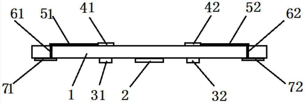
[0014] Such as figure 1 Shown is a thermal wind speed sensor structure with a zero point calibration function, including a circular ceramic substrate 1, a heating element 2 is arranged at the center of the back of the circular ceramic substrate 1, a first temperature measuring sensor 31 and a second measuring sensor The temperature sensors 32 are symmetrically distributed on the back of the circular ceramic substrate 1 with the heating element 2 as the center, and the first heating element 41 and the second heating element 42 are symmetrically distributed on the front of the circular ceramic substrate 1 with the heating element 2 as the center; The first heating element 41 is connected with the first lead pad 71 on the back side of the circular ceramic substrate 1 through the first wire 51 and the first through hole 61, and the second heating element 42 is connected wi...


PUM


Abstract

The invention discloses a thermal wind speed sensor structure and a calibration method with a zero point calibration function. Two heating parts are arranged on the wind sensing surface of the thermal wind speed sensor. The zero point in the current environment can be obtained by taking the arithmetic mean of the two opposite temperature difference signals. The invention has simple structure and convenient packaging, and greatly reduces the detection and calibration time of the thermal wind speed sensor.

Description

technical field [0001] The invention relates to a thermal wind speed sensor structure and a calibration method with a zero point calibration function. Background technique [0002] Wind speed and wind direction are very important parameters to reflect meteorological conditions, and have an important impact on environmental monitoring, air conditioning, and industrial and agricultural production. Therefore, it is of great practical significance to quickly and accurately measure wind speed and wind direction. As we all know, typical thermal anemometers cannot be completely symmetrical due to process and packaging problems. Therefore, the problem of zero drift has always been a major obstacle hindering the improvement of the accuracy and sensitivity of thermal anemometers. The general method is to measure the relationship between the change of ambient temperature and the wind speed, and use a look-up table or empirical formula to calibrate. The problem with this is that a large...

Claims


Application Information

Patent Timeline
Patent Type & Authority Patents(China)
IPC IPC(8): G01P21/02
Inventor 秦明叶一舟陈蓓朱雁青黄庆安
Owner SOUTHEAST UNIV
Learn More