Vibration test clamp for frequency converter

A vibration test and frequency converter technology, applied in vibration testing, machine/structural component testing, manufacturing tools, etc., can solve the problems of occupying the effective bearing capacity of the vibration table, low natural frequency, low rigidity of the vibration fixture, etc., to avoid the test. Error phenomenon, natural frequency increase, effect of reducing fixture quality

Active Publication Date: 2015-10-14
ZHUZHOU CSR TIMES ELECTRIC CO LTD
View PDF6 Cites 1 Cited by
  • Summary
  • Abstract
  • Description
  • Claims
  • Application Information

AI Technical Summary

Problems solved by technology

[0003] The existing frequency converter vibration test fixture design usually lacks necessary calculation analysis and inspection and testing, the vibration transmitted by the fixture is often distorted, and the vibration magnitude of each point on the fixture varies greatly, and there are multi-order resonances in the test frequency band, which affects Test Results
At the same time, the existing vibration test fixture structure cannot guarantee the accuracy of the test results. Specifically, there are the following shortcomings:
[0004] 1) The vibrating fixture uses multiple sets of horizontal beams and vertical beams to realize the positioning of the test piece. The vibrating fixture is heavy, which occupies the effective carrying capacity of the vibrating table and affects the test results;
[0005] 2) The vibration fixture has low rigidity and low natural frequency. The natural frequency of the vibration fixture is close to the natural frequency of the product under test. It is easy to generate resonance during the vibration test, which will affect the test results;
[0006] 3) The specifications of the existing vibration fixtures are fixed. When the same product needs to be placed on different vibration tables for testing, it is necessary to use multiple test fixtures, which is costly

Method used


Image

  • Vibration test clamp for frequency converter
  • Vibration test clamp for frequency converter
  • Vibration test clamp for frequency converter

Examples


Embodiment Construction

[0027] The present invention will be further described in detail in conjunction with the accompanying drawings and specific embodiments.

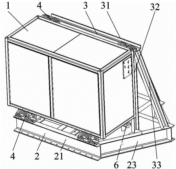
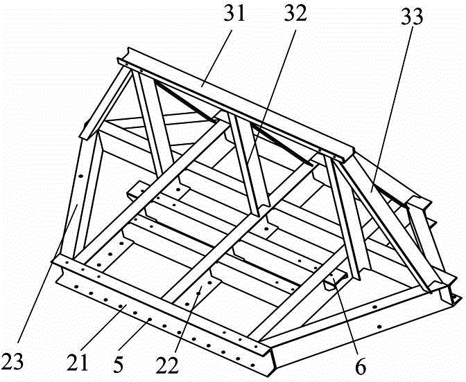
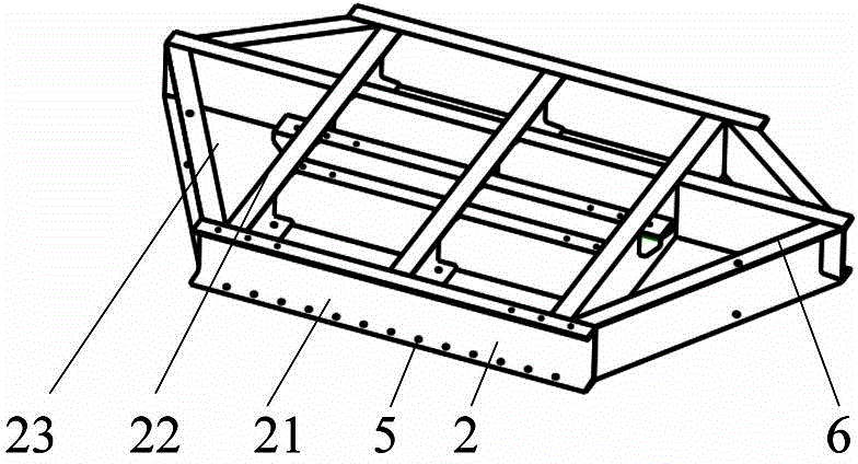
[0028] like Figure 1 to Figure 2 As shown, the vibration test fixture for the frequency converter of this embodiment is used to fix the frequency converter 1 on the vibration platform and transmit the vibration energy to the frequency converter 1. The vibration test fixture for the frequency converter includes a bottom support assembly 2 and a side positioning assembly 3. The support component 2 is supported on the bottom surface of the frequency converter 1, the side positioning component 3 is limited to the side of the frequency converter 1, and the bottom surface support component 2 and the side positioning component 3 mutually vertically position the frequency converter 1, which is convenient for installation. In this embodiment, the bottom surface support assembly 2 includes a bottom surface beam 21, a bottom surface vertical beam 22 ...


PUM


Abstract

The invention provides a vibration test clamp for a frequency converter. The clamp includes a bottom supporting assembly supported on the bottom surface of a frequency converter, and a side surface positioning assembly limited on one side surface of the frequency converter. The bottom supporting assembly is perpendicular to the side surface positioning assembly. The bottom supporting assembly includes a bottom crossbeam, a bottom vertical beam and a bottom inclined draw beam, wherein the bottom crossbeam and the bottom vertical beam cross each other, and the periphery of the bottom crossbeam and the periphery of the bottom vertical beam are connected through the bottom inclined draw beam. The advantages of the vibration test clamp are that the mass is small, the rigid is high, and test errors are minor.

Description

technical field [0001] The invention relates to a test fixture, in particular to a vibration test fixture for a frequency converter. Background technique [0002] With the development of science and technology, the vibration test of large-scale samples puts forward higher requirements for the test equipment, and the test fixture in the test equipment fixes the test article on the vibration platform and transmits the vibration energy to the test article. Therefore, the test fixture is in Plays a key role in the whole vibration test. [0003] The existing frequency converter vibration test fixture design usually lacks necessary calculation analysis and inspection and testing, the vibration transmitted by the fixture is often distorted, and the vibration magnitude of each point on the fixture varies greatly, and there are multi-order resonances in the test frequency band, which affects Test Results. At the same time, the existing vibration test fixture structure cannot guaran...

Claims


Application Information

Patent Timeline
Patent Type & Authority Applications(China)
IPC IPC(8): G01M7/02B25B11/00
Inventor 王磊丁杰宋森刘勇彭希予谢海波徐景秋李碧钰石东山李自然葛会军
Owner ZHUZHOU CSR TIMES ELECTRIC CO LTD
Why Eureka
Try Eureka