
Multi-fire-source identification method based on automatic tracking and positioning jet fire extinguishing device

A fire extinguishing device and automatic tracking technology, which is applied in the field of multi-fire source identification, can solve problems such as the inability to judge the size of the fire, oversaturation of infrared pyroelectric devices, and restrictions on the use of the environment, so as to save system running time and control the spread of fire , Improve the efficiency of fire fighting

Active Publication Date: 2015-10-14
HEFEI KDLIAN SAFETY TECHNOLOGY CO LTD
View PDF8 Cites 16 Cited by
  • Summary
  • Abstract
  • Description
  • Claims
  • Application Information

AI Technical Summary

Problems solved by technology

[0003] In recent years, with the development of various fire sensor technologies, most of the automatic tracking and positioning jet fire extinguishing devices on the market are based on ultraviolet flame sensors and infrared flame sensors. These sensors are generally sensitive to sound, electromagnetic waves and vibrations. There is a certain false alarm rate, and the use environment is subject to certain restrictions
When the fire extinguishing device is close to the flame or there are multiple fire sources in the protected area, there are defects that the fire source cannot be accurately detected and located, and the size of the fire cannot be judged at the same time.
This is mainly due to the fact that most of these devices use infrared energy pyroelectric method for positioning detection, but when the flame energy is too strong, the infrared pyroelectric device is oversaturated and cannot accurately locate the flame energy

Method used


Image

  • Multi-fire-source identification method based on automatic tracking and positioning jet fire extinguishing device
  • Multi-fire-source identification method based on automatic tracking and positioning jet fire extinguishing device
  • Multi-fire-source identification method based on automatic tracking and positioning jet fire extinguishing device

Examples


Embodiment Construction

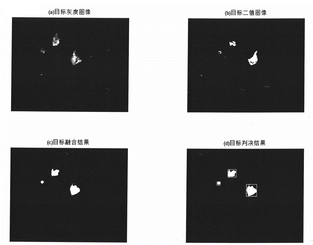
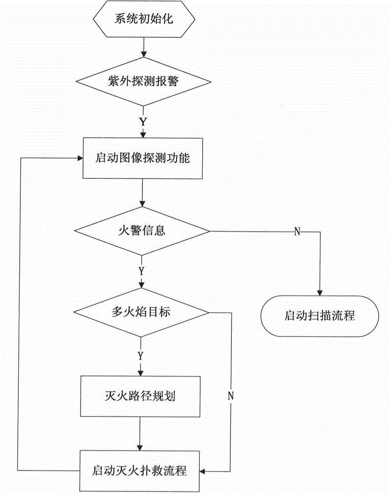
[0040] figure 1 A system flow diagram of a multi-fire source identification method based on automatic tracking and positioning jet fire extinguishing device is given. The overall process of this embodiment is: after the ultraviolet detector of the fire extinguishing device alarms, start the image detection function, if there is fire alarm information in the current field of view, then judge whether there are multiple targets, and if there are multiple targets, perform the fire extinguishing route Planning, target positioning and saving, if there is only one target, directly perform positioning and saving. If there is no flame in the current field of view, the scanning process is started to scan the entire protected area in 360 degrees.

[0041] figure 2 The multi-flame identification method in the scanning process is given: first start the horizontal scanning, the rotation range of the horizontal scanning is 0-360 degrees, start the infrared flame sensor during the horizont...


PUM


Abstract

The invention discloses a multi-fire-source identification method based on an automatic tracking and positioning jet fire extinguishing device. The method comprises the steps: firstly, fire alarm conditions in a protected scope are real-timely monitored by an ultraviolet fire disaster detector in the jet fire extinguishing device, under triggering of fire disaster early warning signals, a video image acquisition module in the fire extinguishing device is started to identify and confirm fire disaster signals, and all flame targets and maximum ignition points thereof are accurately identified through target fusion and segmentation and other ways; and fire disaster positions are accurately positioned by using a computer vision technology, and finally a multi-target fire extinguishing path is planned. The invention aims to provide the method which can automatically identify fire disasters when the fire disasters break out, so as to achieve the purpose of real-time extinguishing of all the fire disasters in the protected region in the one-time scanning working process.

Description

technical field [0001] The invention relates to the technical field of fire detection, in particular to a multi-fire source identification method based on an automatic tracking and positioning jet fire extinguishing device. Background technique [0002] In recent years, my country has achieved certain results in the research of fire monitoring in tall and large spaces. Among them, automatic fire monitors, as an intelligent fire extinguishing system integrating detection, positioning, and fire fighting, have broad development prospects. In some unguarded key protection areas, the technical requirements for fire monitors are getting higher and higher. Finding an efficient automatic fire extinguishing method will become an important direction for the development of fire monitors in the future. [0003] In recent years, with the development of various fire sensor technologies, most of the automatic tracking and positioning jet fire extinguishing devices on the market are based ...

Claims


Application Information

Patent Timeline
Patent Type & Authority Applications(China)
IPC IPC(8): A62C37/00
CPCA62C37/04
Inventor 邓甜甜任士俊郑大为刘健张克年
Owner HEFEI KDLIAN SAFETY TECHNOLOGY CO LTD
Learn More