
Centrifugal rotary conveyer and fish slaughtering machine provided with same

A conveyor and fish technology, applied in the direction of poultry/fish slaughter/stunning, etc., can solve the problems of unsafe slaughter, high labor intensity, high power consumption of equipment, etc., and achieve improved slaughter efficiency, fast slaughter speed, and transportation fast effect

Active Publication Date: 2015-10-14
杜登锋
View PDF13 Cites 0 Cited by
  • Summary
  • Abstract
  • Description
  • Claims
  • Application Information

AI Technical Summary

Problems solved by technology

[0003] In order to solve the problems of high labor intensity and unsafe slaughtering caused by manual slaughtering, loach and eel slaughtering machines have appeared, but the inventors found in the process of realizing the present invention that the existing slaughtering machines still have the following problems : 1. The existing slaughtering machine is to fix the slaughtered object and then send it to the dissection mechanism. For example, take the slaughter of rice field eel as an example. Mechanism, although it solves the problem of stably transporting the eel, but because the skin of the eel is pierced by the needle, the appearance of the eel is seriously damaged after slaughtering, which affects the appearance and taste; 2. The structure of the existing slaughtering machines is relatively complicated. Moreover, a motor is required to drive gears, belts and other conveying mechanisms, resulting in high power consumption of the equipment; 3. The conveying and dissection mechanism of the existing slaughtering machine is relatively slow in operation, and the fastest can only achieve 1.2 seconds per piece, which is still not possible Meet the needs of certain catering industries

Method used


Image

  • Centrifugal rotary conveyer and fish slaughtering machine provided with same
  • Centrifugal rotary conveyer and fish slaughtering machine provided with same
  • Centrifugal rotary conveyer and fish slaughtering machine provided with same

Examples


Embodiment Construction

[0022] The technical solutions in the present invention will be clearly and completely described below in conjunction with the accompanying drawings in the present invention.

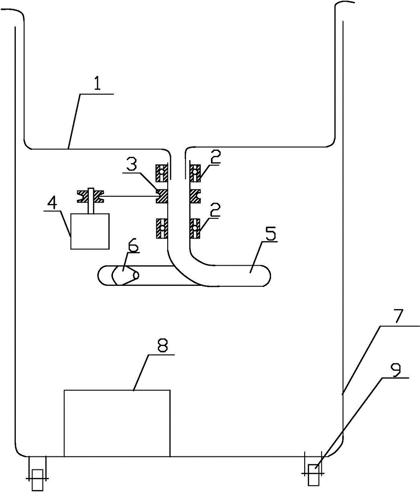
[0023] figure 1 Shown is the structure diagram of the fish slaughtering machine with centrifugal rotary conveyor of the present invention, said fish slaughtering machine with centrifugal rotary conveyor includes centrifugal rotary conveyor and dissection device 6 connected with centrifugal rotary conveyor .

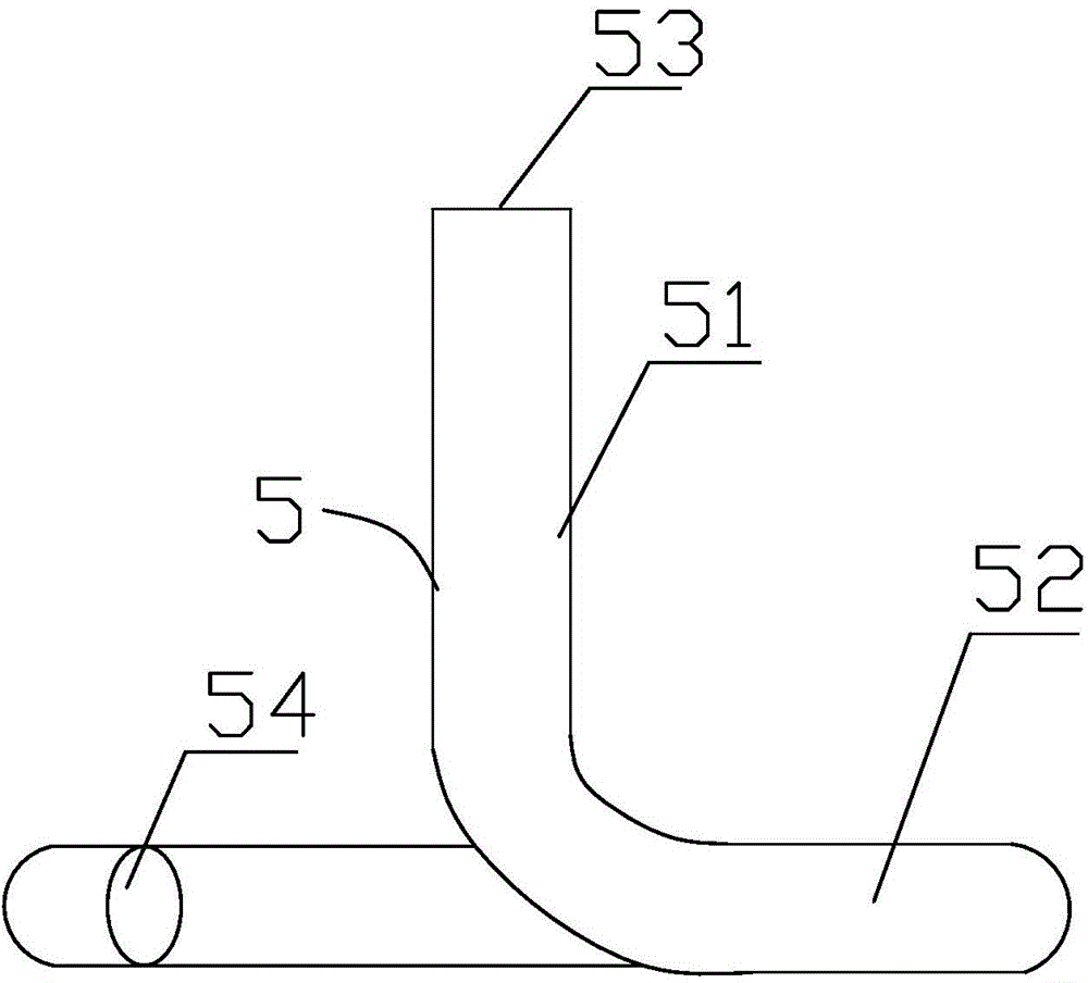
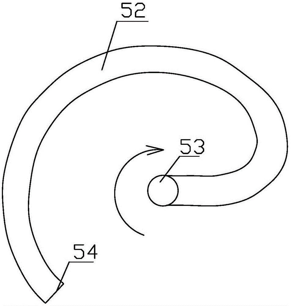
[0024] Please refer to figure 2 and image 3 The centrifugal rotary conveyor includes a storage hopper 1 and an involute rotary pipe 5 installed below the storage hopper 1. The involute rotary pipe 5 includes a vertical pipe body 51 connected to the outlet below the storage hopper 1 and The swivel pipe body 52 connected to the lower end of the vertical pipe body 51, the upper end opening of the vertical pipe body 51 is the swirl pipe inlet 53, which communicates with the outlet below the storag...


PUM


Abstract

The invention provides a centrifugal rotary conveyer which comprises a material storage bucket, a motor, an involute rotary pipe mounted below the materials storage bucket, wherein the involute rotary pipe comprises a vertical pipe body connected with an outlet below the material storage bucket and a rotary pipe body connected with the lower end of the vertical pipe body; the upper opening of the vertical pipe body is a rotary pipe inlet which is communicated with the outlet below the material storage bucket; the bending path of the rotary pipe body is an involute far from the center of the circle of the rotary pipe inlet; the plane of the rotary pipe body is vertical to that of the vertical pipe body; the tail end outlet of the rotary pipe body is a rotary pipe outlet; the involute rotary pipe is driven by the motor to rotate around the axis of the vertical pipe body and the rotary direction is opposite to the revolving direction of the involute. The invention further provides a fish slaughtering machine provided with the centrifugal rotary conveyer. On the premise of not damaging the scarfskin of the slaughtering objects, the fish slaughtering machine can be used for quickly realizing conveyance and slaughtering with relatively low power consumption.

Description

technical field [0001] The invention relates to the technical field of aquatic product processing machinery, in particular to a centrifugal rotary conveyor and a fish slaughtering machine equipped with the centrifugal rotary conveyor. Background technique [0002] Loach, rice field eel and other fish have a layer of protective mucus on the surface of their bodies, which is very difficult to control during the slaughter process, which leads to high intensity and low work efficiency by relying on manual slaughter. The most important thing in the slaughter of fish such as loach and eel is how to stabilize the slaughtered object so that it can be sent to the dissection mechanism safely and quickly, and how to continuously apply the force required for dissection. [0003] In order to solve the problems of high labor intensity and unsafe slaughtering caused by manual slaughtering, loach and eel slaughtering machines have appeared, but the inventors found in the process of realizin...

Claims


Application Information

Patent Timeline
Patent Type & Authority Applications(China)
IPC IPC(8): A22B3/08
CPCA22B3/08
Inventor 刘佳杜登锋
Owner 杜登锋
Learn More