Logic protection emitter coupling type double filtering balanced modulation switching stabilized power supply

A switching regulated power supply, emitter coupling technology, applied in electrical components, output power conversion devices, AC power input into DC power output and other directions, can solve problems such as large ripple coefficient, radio frequency interference, complex circuit, etc. The effect of improving the control range of output current variation, reducing radio frequency interference and simplifying the circuit structure

Inactive Publication Date: 2015-10-07
CHENGDU LEIKEER SCI & TECH
View PDF1 Cites 0 Cited by
  • Summary
  • Abstract
  • Description
  • Claims
  • Application Information

AI Technical Summary

Problems solved by technology

[0004] The purpose of the present invention is to overcome the defects of large ripple coefficient, serious radio frequency interference, complex circuit and low efficiency existing in the current switch-type regulated power supply, and provide a logic-protected emitter-coupled double-filter-type balanced modulation switching regulated power supply

Method used


Image

  • Logic protection emitter coupling type double filtering balanced modulation switching stabilized power supply
  • Logic protection emitter coupling type double filtering balanced modulation switching stabilized power supply
  • Logic protection emitter coupling type double filtering balanced modulation switching stabilized power supply

Examples


Embodiment

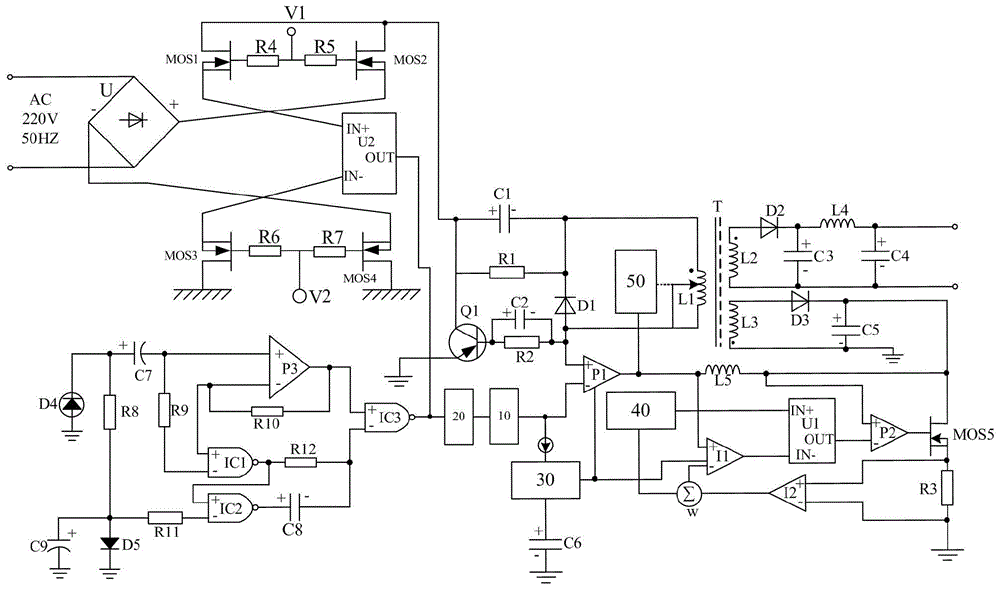
[0026] Such as figure 1 As shown, the present invention mainly consists of diode rectifier U, power amplifier P1, voltage comparator U2, transformer T, balance adjustment circuit, switching filter circuit, power output circuit, transformer feedback circuit, switching control circuit, oscillator 40, current comparison It is composed of a filter I1, a current comparator I2, a slope compensator W, a PWM controller 30, a sliding regulator, and a double filter amplifier circuit 10, a beam excitation type logic amplifier circuit, and a logic protection emitter coupling type amplifier circuit 20.

[0027] Among them, the transformer T is composed of a primary coil L1 arranged on the primary side, a secondary coil L2 and a secondary coil L3 arranged on the secondary side. In the present invention, a sliding tap is provided on the primary coil L1 of the transformer T, and the sliding tap is controlled by a sliding regulator to ensure the adjustment according to the common result of the dut...


PUM


Abstract

The invention discloses a balanced modulation switching stabilized power supply based on a light beam excitation type and a logic protection emitter coupling type. The balanced modulation switching stabilized power supply is mainly composed of a diode rectifier U, a power amplifier P1, a voltage comparator U2, a transformer T, a balance adjustment circuit connected between the diode rectifier U and the voltage comparator U2 in series, a switch filtering circuit connected between the balance adjustment circuit and the power amplifier P1 in series, a power output circuit connected with a secondary coil L2 of the transformer T and the like. The balanced modulation switching stabilized power supply is characterized by further comprising a light beam excitation type logic amplifying circuit and a logic protection emitter coupling type amplifying circuit, the light beam excitation type logic amplifying circuit is connected with a PWM controller, the power amplifier P1 and the voltage comparator U2, and the logic protection emitter coupling type amplifying circuit is connected between the light beam excitation type logic amplifying circuit and the power amplifier P1 in series. The light beam excitation type logic amplifying circuit and the control function of PWM are fully combined together, a power output voltage value can be automatically adjusted according to the duty ratio, and the stability of the output value is ensured.

Description

Technical field [0001] The invention relates to a switch regulated power supply, in particular to a logic protection emitter coupling type double filter type balanced modulation switch regulated power supply. Background technique [0002] With the continuous advancement of current technology, electronic products are becoming more and more powerful while also bringing great convenience to people's lives. The voltage stabilizing circuit is born out of operation. The traditional series linear adjusting voltage stabilizing circuit has the characteristics of high stability, adjustable output voltage, small ripple coefficient and simple circuit. However, the regulator tubes of these series linear regulator circuits always work in an amplifying state, and current flows all the time. Therefore, the power consumption of the tubes is relatively large, and the efficiency of the circuit is not high, generally only reaching 30% to 50%. %about. In order to overcome the above-mentioned shortc...

Claims


Application Information

Patent Timeline
Patent Type & Authority Applications(China)
IPC IPC(8): H02M7/217H02M1/44H02M1/15
CPCH02M1/44H02M7/2176
Inventor 黄涛
Owner CHENGDU LEIKEER SCI & TECH
Why Eureka
Try Eureka