
Concentrated magnetic passive rotor transverse flux single-phase motor

A passive rotor, transverse magnetic flux technology, applied in synchronous machines, electrical components, electromechanical devices, etc., can solve the problem of low utilization rate of permanent magnets, and achieve the effect of reducing copper loss, improving utilization rate, and simplifying core structure

Active Publication Date: 2017-05-10
NANJING UNIV OF AERONAUTICS & ASTRONAUTICS
View PDF2 Cites 0 Cited by
  • Summary
  • Abstract
  • Description
  • Claims
  • Application Information

AI Technical Summary

Problems solved by technology

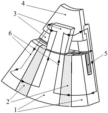
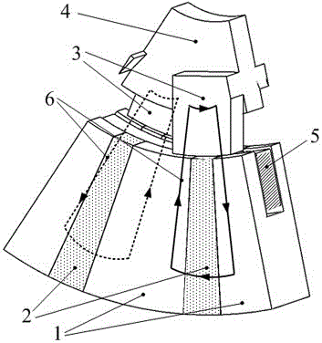
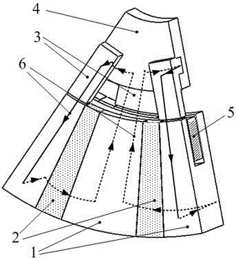
[0011] The technical problem to be solved by the present invention is to aim at the deficiency of the above-mentioned background technology, and provide a magnetism-concentrating passive rotor transverse flux single-phase motor, which realizes that each permanent magnet can provide effective magnetic motion when the windings are interlinked with the maximum permanent magnet flux linkage. Potential, solves the technical problem of low utilization rate of permanent magnets in existing passive rotor transverse flux motors

Method used


Image

  • Concentrated magnetic passive rotor transverse flux single-phase motor
  • Concentrated magnetic passive rotor transverse flux single-phase motor
  • Concentrated magnetic passive rotor transverse flux single-phase motor

Examples


Embodiment Construction

[0036] Embodiments of the present invention will be described in detail below, and the embodiments described below with reference to the accompanying drawings are exemplary, and are only used to explain the present invention, and cannot be construed as limiting the present invention.

[0037] Those skilled in the art can understand that, unless otherwise defined, all terms (including technical terms and scientific terms) used herein have the same meaning as commonly understood by one of ordinary skill in the art to which this invention belongs. It should also be understood that terms such as those defined in commonly used dictionaries should be understood to have a meaning consistent with the meaning in the context of the prior art, and will not be interpreted in an idealized or overly formal sense unless defined as herein explain.

[0038] In order to facilitate the understanding of the embodiments of the present invention, several specific embodiments will be taken as exampl...


PUM


Abstract

The invention discloses a magnetism gathering passive rotor transverse magnetic flux single-phase motor, and belongs to the transverse magnetic flux motor technology field. The single-phase motor comprises a stator composed of C-shaped stator iron cores and C-shaped permanent magnets, a rotor composed of an L-shaped rotor iron core and a rotor annular magnetic conductive structure, an annular armature winding. The C-shaped stator iron cores and the C-shaped permanent magnets are arranged alternatively in the circumference, and the C-shaped permanent magnets magnetize in the circumferential direction and the magnetization directions of two adjacent C-shaped permanent magnets are opposite. The annular armature winding is wound in the recessed groove formed after the C-shaped stator iron cores and the C-shaped permanent magnets are arranged alternatively. Grooves for insertion of L-shaped rotor iron cores in uniform distribution are formed in the rotor annular magnetic conductive structure. The C-shaped permanent magnets provide an effective magnetomotive force when a main excitation path formed among the rotor, the air gap and the stator goes through the yoke section of the rotor, and the permanent magnet utilization rate is raised.

Description

technical field [0001] The invention discloses a magnetic flux gathering type passive rotor transverse flux single-phase motor, which belongs to the technical field of transverse flux motors. Background technique [0002] Transverse flux permanent magnet motor is a new type of motor proposed by German Professor H.Web in the 1980s. Compared with traditional permanent magnet motors, the magnetic field of this motor is three-dimensionally distributed, and it is in a different plane from the winding, which can take into account The cross-sectional area of ​​the winding and the cross-sectional area of ​​the stator tooth poles increase the torque density of the motor. The prototype motor he proposed and the subsequent modified motors all belong to the surface-mounted permanent magnet structure. The number of permanent magnets is large and the utilization rate is not high. [0003] Rolls-Royce's double-sided magnetic-concentration structure TFM uses a C-shaped stator core, and the...

Claims


Application Information

Patent Timeline
Patent Type & Authority Patents(China)
IPC IPC(8): H02K21/00H02K21/04
Inventor 陈志辉何海翔王兰凤赵凯弟
Owner NANJING UNIV OF AERONAUTICS & ASTRONAUTICS
Learn More