Dust and mist removal equipment, treatment tower and its application
A demisting equipment and equipment technology, applied to the separation of dispersed particles, chemical instruments and methods, combined devices, etc., can solve the problems of power consumption, increase the difficulty of water balance in the desulfurization system, increase operating costs, etc., and achieve improved demisting efficiency , Excellent dust and fog removal effect, saving equipment and operating costs
- Summary
- Abstract
- Description
- Claims
- Application Information
AI Technical Summary
Problems solved by technology
Method used
Image
Examples
Embodiment approach
[0050] In the present invention, the spray unit includes a dedusting liquid nozzle, and the dedusting liquid nozzle is arranged on the central axis and above the rotating blade group, and is used for supplying dedusting liquid to the inside of the guide cylinder. According to actual needs, one or more layers of dedusting liquid nozzles can be set, and the specific position, quantity and angle of the nozzles can be set according to the actual needs of dedusting and demisting. In the spray unit of the present invention, preferably, the number of the dedusting liquid nozzles is at least 2, more preferably 2-6. The included angle between the dedusting liquid nozzle and the vertical direction is 60-150°, preferably 90-120°. According to an embodiment of the present invention, the number of the dedusting liquid nozzles is 4, and the included angle with the vertical direction is 120°. According to a preferred embodiment of the present invention, the nozzle is located at about 1 / 2 of...
Embodiment 1
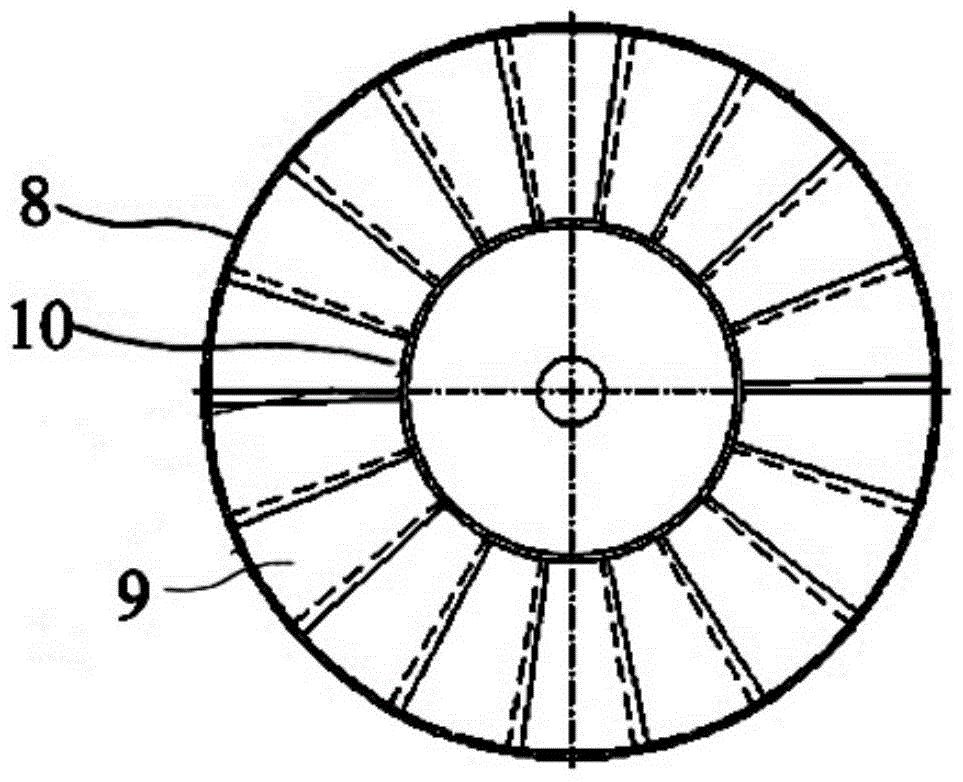
[0075] figure 1 It is a schematic diagram of the dust removal and mist removal equipment of the present invention, figure 2 It is a schematic diagram of the structure of the rotating blade group. The dust and mist removal equipment of the present invention includes a cylindrical guide tube 1, a central axis 4 is arranged on the central axis of symmetry inside the guide tube 1, and the central axis 4 passes through the first hub 51 and the second hub 52 It is fixed together with the guide tube 1, wherein the first hub 51 is a hollow structure, which is bonded and fixed with the central shaft 4 and the guide tube 1 respectively, and the second hub 52 is a solid structure, which is bonded and fixed with the central shaft 4. It is fixed with the guide tube 1 by screws.
[0076] A layer of rotating vane sets 2 is provided at the lower part of the guide tube 1 . The rotating blade set 2 includes an outer cylinder 8 , a blade set 9 and a central cylinder 10 . The outer cylinder ...
Embodiment 2
[0079]Change the angle of elevation of all blades to be 45°, and other conditions are the same as in Example 1.
PUM
| Property | Measurement | Unit |
|---|---|---|
| angle | aaaaa | aaaaa |
| angle | aaaaa | aaaaa |
Abstract
Description
Claims
Application Information
 - R&D
- Intellectual Property
- Life Sciences
- Materials
- Tech Scout
- Unparalleled Data Quality
- Higher Quality Content
- 60% Fewer Hallucinations
Browse by: Latest US Patents, China's latest patents, Technical Efficacy Thesaurus, Application Domain, Technology Topic, Popular Technical Reports.
© 2025 PatSnap. All rights reserved.Legal|Privacy policy|Modern Slavery Act Transparency Statement|Sitemap|About US| Contact US: help@patsnap.com


