
Working fluid container with predetermined breaking point

A technology for working fluid and container, which is applied in the field of containers for storing working fluid, for example, can solve problems such as failure to achieve a fracture effect, and achieve the effect of low production cost

Inactive Publication Date: 2016-10-19
KAUTEX TEXTRON
View PDF5 Cites 0 Cited by
  • Summary
  • Abstract
  • Description
  • Claims
  • Application Information

AI Technical Summary

Problems solved by technology

However, at higher temperatures such as +60°C and a slow increase in load (especially due to internal pressurization), this intended breaking effect cannot be achieved

Method used


Image

  • Working fluid container with predetermined breaking point
  • Working fluid container with predetermined breaking point
  • Working fluid container with predetermined breaking point

Examples


Embodiment Construction

[0040] In the following description, the same reference numerals denote the same components or the same features, so descriptions about one component in one drawing are also applicable to other drawings, thereby avoiding repeated descriptions.

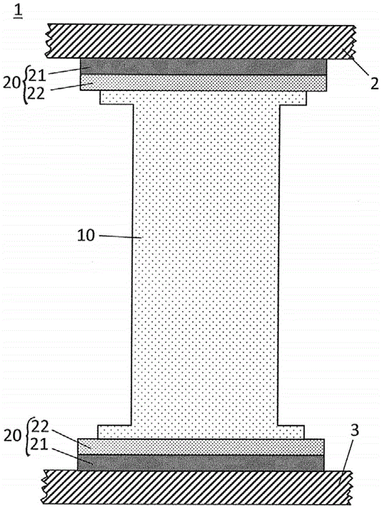
[0041] figure 1 A cross section of the operating fluid container 1 reinforced by the reinforcing element 10 is shown. The reinforcing element 10 is arranged between the two container walls 2 , 3 of the operating fluid container. In this case, the container wall 2 is designed as the upper housing 2 and the container wall 3 is designed as the lower housing 3 of the operating fluid container 1 .

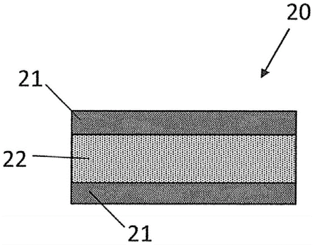
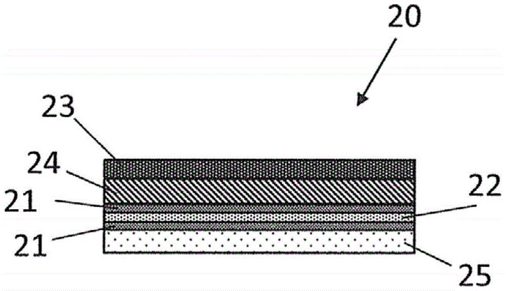
[0042] The respective connecting element 20 is arranged between the respective end region of the reinforcing element 10 and the upper housing 2 and the lower housing 3 . In the exemplary embodiment shown, each connecting element 20 comprises at least two material layers 21 , 22 connected to each other. The first material layer 21 may be a lay...


PUM


Abstract

The present invention relates to an operating fluid container (1) composed of thermoplastic for a motor vehicle, comprising a reinforcing element (10; 11, 12), which is arranged between two container walls (2, 3) of the operating fluid container (1) and is at least indirectly joined to the container walls (2, 3). The operating fluid container (1) according to the invention is characterized by the fact that the container walls (2, 3) are joined to one another indirectly via the reinforcing element (10; 11, 12) by means of at least one joining element (20; 21-25). In this arrangement, the joining element (20; 21-25) comprises at least two material layers (21-25) joined to one another, wherein a joining force joining the two material layers (21, 22) to one another is less than a joining force between the joining elements (20; 21-25) and the container wall (2, 3) and / or between the joining element (20; 21-25) and the reinforcing element (10; 11, 12).

Description

technical field [0001] The invention relates to a thermoplastic fluid container for a motor vehicle. [0002] A working fluid container in the sense of the present invention may be a fuel tank, a container for storing an aqueous urea solution for the selective catalytic reduction of nitrogen oxides in exhaust gases, a wiper fluid container, or more generally any other container for storing e.g. Container for working fluid. Background technique [0003] In the case of operating fluid containers known from the prior art, reinforcing elements are arranged inside the operating fluid container to reinforce it, wherein the reinforcing elements are usually connected to the upper and lower housings of the operating fluid container. The reinforcement element and the respective container shell are materially connected, for example by gluing or welding. However, positive joinings by riveting, screwing or by bayonet connections are also possible. [0004] Operating fluid containers i...

Claims


Application Information

Patent Timeline
Patent Type & Authority Patents(China)
IPC IPC(8): B60K15/03
CPCB60K15/03177B60K2015/03493
Inventor 乌尔里奇·卡施
Owner KAUTEX TEXTRON
Learn More