Charging device and electronic equipment
A charging device and rechargeable battery technology, applied in the electronic field, can solve the problems of frequent charging of wearable electronic devices, achieve the effect of reducing the charging frequency and prolonging the use time
- Summary
- Abstract
- Description
- Claims
- Application Information
AI Technical Summary
Problems solved by technology
Method used
Image
Examples
Embodiment 1
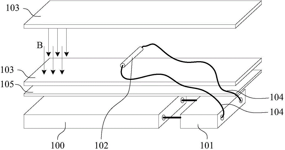
[0028] An embodiment of the present invention provides an electronic device, which may specifically be a wearable electronic device such as a smart watch. In this embodiment, a smart watch is taken as an example for illustration, such as figure 1 As shown, the power module in the smart watch is composed of a main battery 100 and a charging device.
[0029] Wherein, the charging device includes a magnetoelectric component and a rechargeable battery 101 . When the user wears the smart watch for exercise, the charging device in the smart watch will also move accordingly. At this time, the magnetoelectric component can generate electrical energy, that is, convert mechanical energy into electrical energy, and the electrical energy generated by the magnetoelectric component will be charged into the rechargeable battery. 101.
[0030] The magnetoelectric assembly specifically includes a magnetic pole part for generating a magnetic field, and a movable conductor 102 , the two ends o...
Embodiment 2
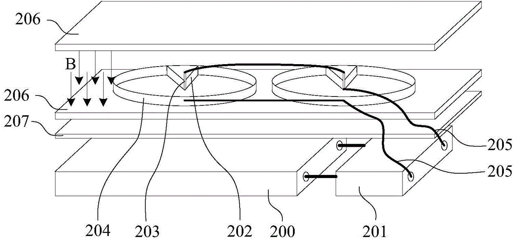
[0038] This embodiment provides a smart watch, in which the power module is basically the same as that of Embodiment 1, including a main battery 200 and a charging device. The charging device includes a magnetoelectric component and a rechargeable battery 201 , and a magnetic isolation plate 207 is provided between the magnetoelectric component, the rechargeable battery 201 and the main battery 200 .
[0039] The difference between this embodiment and Embodiment 1 is that, if figure 2 As shown, in this embodiment, the conductor 202 is placed in the magnetic field B formed by the magnetic pole plate 206 through the rotating shaft 203. When the charging device moves, the conductor 202 rotates around the rotating shaft 203, thereby cutting the magnetic field lines and generating an induced current.
[0040] As a preferred solution, the conductor 202 in this embodiment is fan-shaped, and the rotating shaft 203 is set at the center of the conductor 202 . The periphery of the cond...
PUM
 Abstract
Description
Claims
Application Information
 - R&D
- Intellectual Property
- Life Sciences
- Materials
- Tech Scout
- Unparalleled Data Quality
- Higher Quality Content
- 60% Fewer Hallucinations
Browse by: Latest US Patents, China's latest patents, Technical Efficacy Thesaurus, Application Domain, Technology Topic, Popular Technical Reports.
© 2025 PatSnap. All rights reserved.Legal|Privacy policy|Modern Slavery Act Transparency Statement|Sitemap|About US| Contact US: help@patsnap.com


