


Quick Research
Generate reliable direction feasibility study reports for your R&D in just a few steps.

Technical Q&A
Discover and master advanced knowledge NOW. Basics, ideas, possibilities, all at once.

Find Solutions
As an expert in R&D theories, this can generate solutions to your technical problems instantly.

Evaluate Feasibility
Analyze your overall solution with one click, know your potential R&D risks in advance.

Monitor Landscape
Get weekly tech updates, stay abreast of the latest tech innovations and key insights.
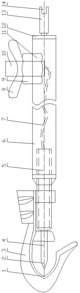
Multifunctional relay protection polarity test operating rod
A technology of relay protection and polarity testing, which is applied in the direction of measuring electricity, measuring devices, measuring electrical variables, etc., can solve the problems that cannot meet the actual needs of the site, threaten the personal safety of operators, and narrow the internal space of the cabinet, etc., to achieve Improve the scope of use, avoid bad contact, and simple structure
- Summary
- Abstract
- Description
- Claims
- Application Information
AI Technical Summary
Problems solved by technology
Method used
Image

Examples
Embodiment Construction
[0024] The present invention will be further described in detail below through the specific examples, the following examples are only descriptive, not restrictive, and cannot limit the protection scope of the present invention with this.
[0025] The structures, connections and detection methods not described in detail in the present invention can be understood as common knowledge in the field.
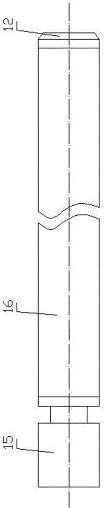
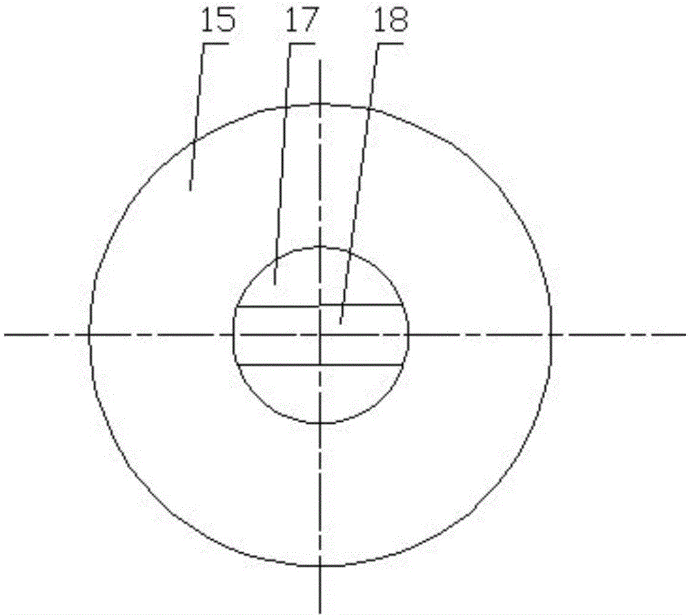
[0026] A multifunctional relay protection polarity test operating lever, such as figure 1 As shown, the operating rod includes a copper hook 3, a metal thorn point 4, a conductive screw 5, a wire 7, an operating mandrel 6 and a terminal post 10, and a wire is arranged in the operating mandrel, and one end of the conducting screw is the same as The shaft extends into the operating mandrel and its end is connected with one end of the wire. The conductive screw is fixed with the operating mandrel. The other end of the conductive screw is coaxially fixed with a metal thorn. The copper hoo...
PUM
 Abstract
Description
Claims
Application Information
 - R&D Engineer
- R&D Manager
- IP Professional
- Industry Leading Data Capabilities
- Powerful AI technology
- Patent DNA Extraction
Browse by: Latest US Patents, China's latest patents, Technical Efficacy Thesaurus, Application Domain, Technology Topic, Popular Technical Reports.
© 2024 PatSnap. All rights reserved.Legal|Privacy policy|Modern Slavery Act Transparency Statement|Sitemap|About US| Contact US: help@patsnap.com