
Automatic replacement control system and method for line drop switch based on laser technology

A drop switch and control method technology, applied in overhead lines/cable equipment, manufacturing tools, manipulators, etc., can solve problems such as loss of texture information, difficulty in accurately controlling the penetration of bolts into bolt apertures, and the inability of control systems to achieve target tracking, etc. Achieve the effect of reducing difficulty and facilitating positioning and tracking

Active Publication Date: 2017-01-18
STATE GRID INTELLIGENCE TECH CO LTD
View PDF5 Cites 0 Cited by
  • Summary
  • Abstract
  • Description
  • Claims
  • Application Information

AI Technical Summary

Problems solved by technology

[0007] (1) The gray scale of the bolt clamped by the mechanical arm in the image captured by the camera is very similar to that of other electrical equipment and brackets around it, which makes the control system unsuitable for target tracking
[0008] (2) The bolt is relatively small in the image acquired by the camera, and the texture information formed by its own thread will be lost, which increases the difficulty of the control system to track and locate the bolt
[0009] (3) The outer diameter of the bolt is very close to the inner diameter of the bolt hole, and it is difficult to accurately control the bolt extending into the bolt hole

Method used


Image

  • Automatic replacement control system and method for line drop switch based on laser technology
  • Automatic replacement control system and method for line drop switch based on laser technology
  • Automatic replacement control system and method for line drop switch based on laser technology

Examples


Embodiment Construction

[0053] The present invention will be further described below in conjunction with the accompanying drawings and embodiments.

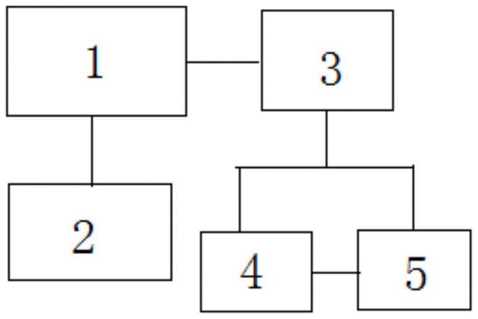
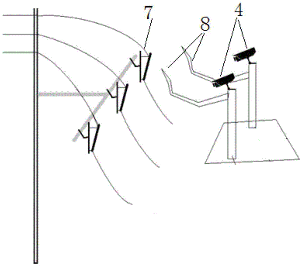
[0054] Such as Figure 1-2As shown, the line drop switch automatic replacement control system based on laser technology is characterized in that it includes:

[0055] Robot control unit 1: used to receive data from the data processing center and send control commands to the robotic arm control unit;

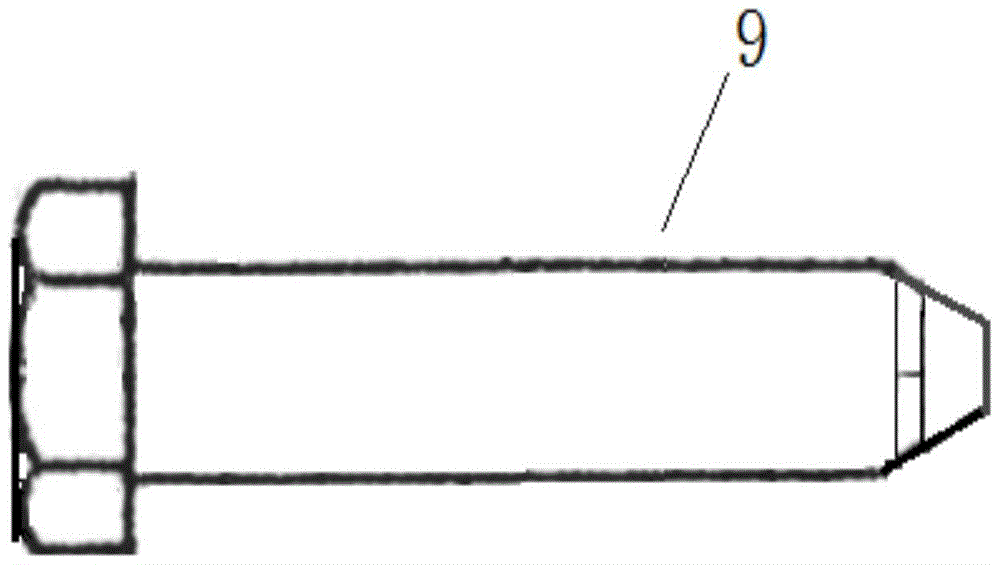
[0056] Manipulator control unit 2: used to control the manipulator 8 of the robot to replace the drop switch 7 by tightening or unscrewing the bolt 9 with identification information;

[0057] Laser positioning module 4: used to obtain the three-dimensional point cloud information of the front end of the mechanical arm 8 and transmit the information to the data processing center;

[0058] Target tracking module 5: Use the 3D point cloud information collected by the laser positioning module to calculate the movement of the current target of interest in rea...


PUM


Abstract

The invention discloses an automatic changing control system and an automatic changing control method on the basis of laser technologies for line dropping switches. The automatic changing control system comprises a robot control unit, a mechanical arm control unit, a laser positioning module, a target tracking module and a data processing center. The robot control unit is connected with the data processing center and the mechanical arm control unit, the data processing center is connected with the laser positioning module and the target tracking module, the laser positioning module is connected with the target tracking module, and mechanical arms of robots can complete dropping switch changing operation under the control of the mechanical arm control unit. The automatic changing control system and the automatic changing control method have the advantages that the dropping switches in high-voltage power transmission lines can be changed by the mechanical arms under automatic precise control of the automatic changing control system and the automatic changing control method, bolts with identification information are tracked and positioned by the aid of the target tracking module, can be accurately identified by the mechanical arms under the control of the automatic changing control system and the automatic changing control method and then can be screwed in or out, and accordingly the dropping switches can be automatically changed.

Description

technical field [0001] The invention relates to the field of machine vision, in particular to a control system and method for automatic replacement of line drop switches based on laser technology. Background technique [0002] Traditional power equipment maintenance requires manual close contact with equipment, which not only threatens the personal safety of construction personnel, but also is inefficient. With the development of artificial intelligence, machine vision and other related technologies, operations in various high-risk environments have begun to be replaced by robots, and equipment maintenance of high-voltage transmission lines can also be completed by robots. [0003] The drop switch is an indispensable device in the high-voltage transmission line. When the current in the line is too large, the fuse in the drop switch will be heated and blown due to the excessive current, so as to achieve the purpose of protecting the line. Usually, after the drop switch is fu...

Claims


Application Information

Patent Timeline
Patent Type & Authority Patents(China)
IPC IPC(8): B25J13/08H02G1/02
Inventor 鲁守银韩磊王振利慕世友任杰傅孟潮谭林李健吕曦晨赵亚博李建祥赵金龙陈强高郎宏
Owner STATE GRID INTELLIGENCE TECH CO LTD
Learn More