Vehicular brake hydraulic pressure controller

A brake hydraulic pressure and control device technology, applied in the direction of brakes, brake components, vehicle parts, etc., to achieve the effect of saving space

Active Publication Date: 2015-09-23
AUTOLIV NISSIN BRAKE SYST JAPAN CO LTD
View PDF6 Cites 5 Cited by
  • Summary
  • Abstract
  • Description
  • Claims
  • Application Information

AI Technical Summary

Problems solved by technology

[0009] However, the additional arrangement of the caliper pressure sensor has the problem of easily increasing the size of the substrate.

Method used


Image

  • Vehicular brake hydraulic pressure controller
  • Vehicular brake hydraulic pressure controller
  • Vehicular brake hydraulic pressure controller

Examples


Embodiment Construction

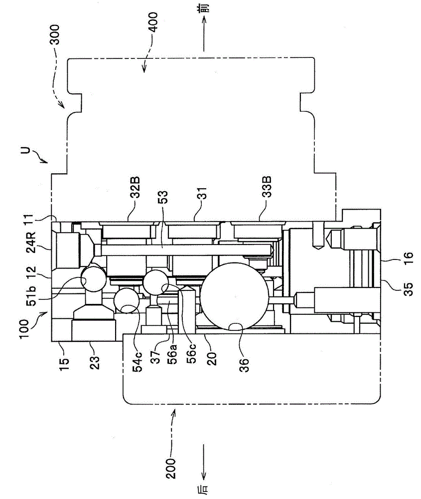
[0048] Hereinafter, modes for implementing the present invention will be described in detail with reference to the drawings. It should be noted that, in the description, the same reference numerals are attached to the same elements, and overlapping descriptions are omitted. In addition, in the following description, the term "up and down" is used with reference to the state where the inlet port 21, the outlet port 22L, etc., which will be described later, of the base body 100 are up and the pair of reservoirs 5 is down, but this is not necessarily the case. Consistent with the actual setting state.

[0049] Such as figure 1 As shown, the vehicle brake fluid pressure control device (hereinafter referred to as "brake fluid pressure control device") U of this embodiment is used in four-wheeled vehicles and the like, and includes: a base 100; The motor 200 (electric motor) on (the other side, the motor installation surface); the controller housing 300 assembled on the front surf...


PUM


Abstract

In the present invention, a base is reduced in size despite the presence of a caliper pressure sensor. An inlet port and an outlet port are disposed in the top part of a base (100); a reservoir (5) is disposed in the bottom part of the base; a pair of pumps (6) are disposed between the inlet port and the reservoir; a pressure booster valve, a depressurizing valve, a cut valve, and a caliper pressure sensor are disposed in a row in a direction along the center axis of each pump; the pressure booster valve is disposed above the center axis (Y1) of the pump; the depressurizing valve is disposed below the center axis of the pump; the cut valve is disposed between the pressure booster valve and the depressurizing valve and is also disposed nearer the middle of the base than the pressure booster valve and the depressurizing valve disposed at the end of the base; and a suction valve (4) is disposed between the depressurizing valves that, of the depressurizing valves aligned in the direction along the center axes of the pumps, are aligned nearer the end of the base than a vertical reference line passing through the rotational center axes of the pumps. The suction valve communicates with a pair of cut valves, and a master pressure sensor (8) is disposed on the reference line of the base.

Description

technical field [0001] The present invention relates to a vehicle brake fluid pressure control device used in a vehicle (for example, a motor vehicle, a motorcycle, a motorcycle, an all-terrain vehicle (ATV), and the like). Background technique [0002] All the time, this kind of brake hydraulic pressure control device for vehicles has a base body, the base body is formed with a flow path for the brake fluid to flow, and the solenoid valve, pump, etc. for controlling the flow of the brake fluid are installed on the base body (for example, refer to the patent Literature 1). [0003] prior art literature [0004] patent documents [0005] Patent Document 1: Japanese Patent No. 4760595 [0006] Summary of the invention [0007] The problem to be solved by the invention [0008] However, as a running function of a vehicle equipped with a brake hydraulic pressure control device for a vehicle, a traffic jam follow-up function of starting and stopping the own vehicle according...

Claims


Application Information

Patent Timeline
Patent Type & Authority Applications(China)
IPC IPC(8): B60T8/34
CPCB60T8/368B60T8/4872B60T13/686
Inventor 袰谷正俊
Owner AUTOLIV NISSIN BRAKE SYST JAPAN CO LTD
Why Eureka
Try Eureka