
Thermophotovoltaic power generation device and method during continuous casting process

A technology of thermal photovoltaic cells and castings, applied in the field of thermal photovoltaic power generation devices in the continuous casting process, can solve the problems of large heat exchange temperature difference between castings and cooling water, heat loss, heat depreciation utilization, etc., to achieve low power generation costs, small heat dissipation losses, Good cooling effect

Inactive Publication Date: 2015-09-23
JIMEI UNIV
View PDF4 Cites 2 Cited by
  • Summary
  • Abstract
  • Description
  • Claims
  • Application Information

AI Technical Summary

Problems solved by technology

Taking continuous steel casting as an example, the surface temperature of the steel ingot pulled out from the crystallizer during the continuous casting process is generally around 1300-1500K, and after passing through the secondary cooling zone, the surface temperature drops to around 950-1100K. After entering the air cooling zone, due to The heat transfer from the center of the steel ingot to the surface, the surface temperature of the steel ingot rises to about 1100~1200K. From the above analysis, it can be seen that the casting in the continuous casting process can be regarded as a high-temperature heat radiator that continuously emits infrared rays to the outside, and the casting and cooling in the secondary cooling zone The heat exchange temperature difference of water is very large, and the heat in this link is seriously depreciated and utilized, resulting in a huge heat loss

Method used


Image

  • Thermophotovoltaic power generation device and method during continuous casting process
  • Thermophotovoltaic power generation device and method during continuous casting process

Examples


Embodiment Construction

[0022] 1. Device

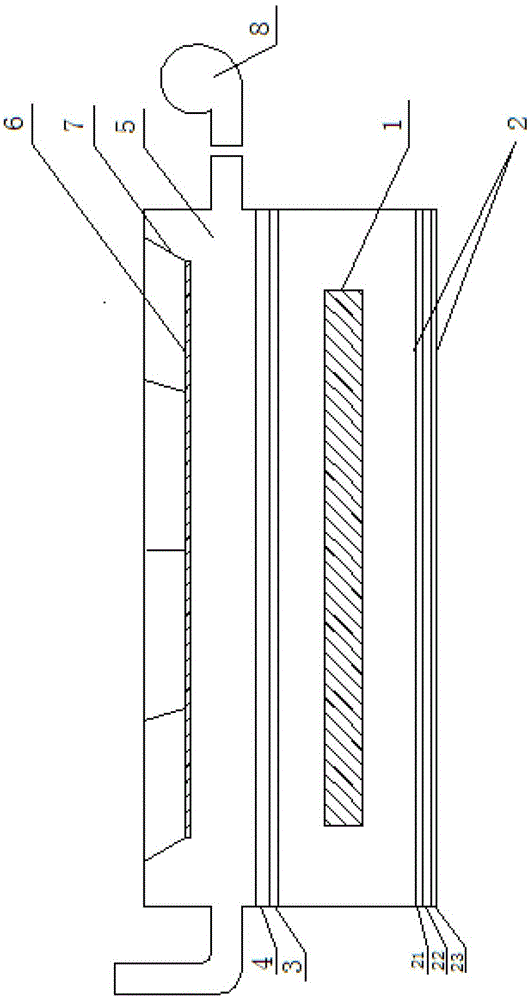
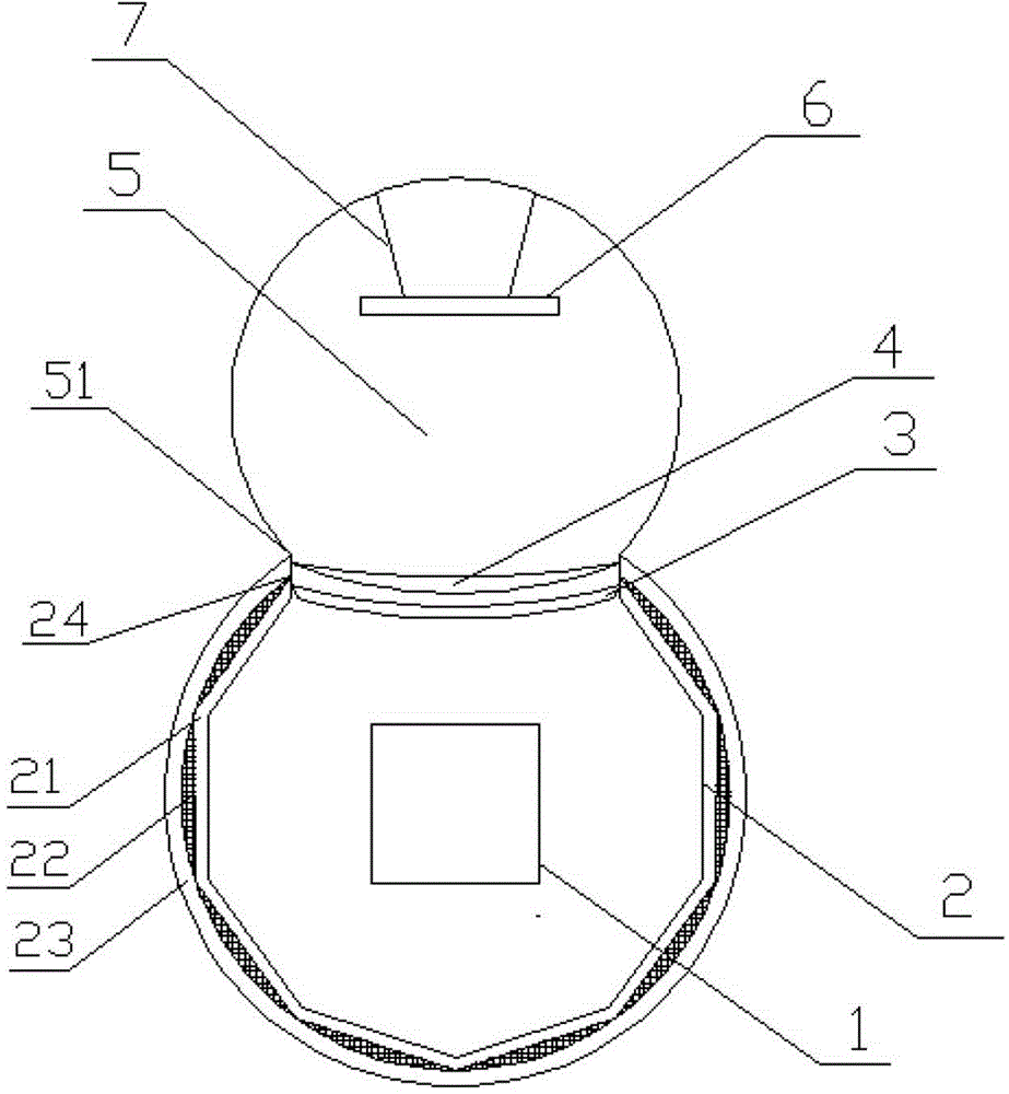
[0023] Such as figure 1 , figure 2 As shown, the present invention is a thermal photovoltaic power generation device for continuous casting process, which includes high temperature casting 1, reflecting wall 2, optical filter assembly 3, linear Fresnel lens assembly 4, cooling air channel 5, liquid immersion thermal photovoltaic Battery panel assembly 6, bracket 7, cooling fan 8.

[0024] The high-temperature casting 1 is a continuously moving casting that is pulled out from the mold during the continuous casting process until it is cut; the reflecting wall 2 is a bendable cylindrical cavity structure, and the reflecting wall 2 surrounds the high-temperature casting 1 in it Inner cavity, and the central axis of the reflective wall 2 is consistent with the central axis of the high-temperature casting 1. The reflective wall 2 has a three-layer structure, the innermost layer is a transmission material 21 made of high-purity quartz glass, and the middle layer is ma...


PUM


Abstract

The invention discloses a thermophotovoltaic power generation device and method during continuous casting process. The thermophotovoltaic power generation device comprises a high-temperature casting, a reflection wall, an optical filter module, a linear Fresnel lens module, a cooling air channel, an immersed thermophotovoltaic cell panel module, a support and a cooling fan, wherein light rays peripherally emitted from the high-temperature casting are reflected by the reflection wall many times and reach the optical filter module, the light rays which can be absorbed by a thermophotvoltaic cell pass through the optical filter, reach the linear Fresnel lens module, and focused on the cell surface of the immersed thermophotovoltaic cell panel module by passing through the linear Fresnel lens, and thus thermophotovoltaic power generation and electric energy output are achieved. The cooling fan is used for providing cooling air for the cooling air channel and timely removing dissipation heat of the immersed thermophotovoltaic cell so that the immersed thermophotovoltaic cell is kept at a low temperature. The thermophotovoltaic power generation device has the characteristics of high energy utilization rate, high power generation efficiency, low power generation cost, low heat dissipation loss, long service life of the battery, running reliability, convenience in installation and maintenance and the like, and can be widely applied to the continuous casting process in metallurgical industry.

Description

technical field [0001] The invention belongs to the technical field of thermal photovoltaic power generation, and in particular relates to a continuous casting process thermal photovoltaic power generation device and a method thereof. Background technique [0002] Thermal photovoltaic power generation technology is a technology that projects infrared radiation energy (wavelength 800-2000nm) of a high-temperature (temperature 1000-2000k) thermal radiator onto a thermal photovoltaic cell to convert it into electrical energy. Compared with solar photovoltaic power generation technology, thermal photovoltaic power generation technology has the characteristics of not relying on sunlight, and can provide stable electric energy without being affected by day and night, seasons or weather, and has higher energy output density and theoretical conversion efficiency. Therefore, Thermal photovoltaic power generation technology has attracted more and more attention. At present, some ther...

Claims


Application Information

Patent Timeline
IPC IPC(8): H02S10/30H02S40/22H02S40/42
CPCH01L31/0521H02S10/00H02S40/00Y02E10/52
Inventor 陈志强杨绍辉黄晓娟欧鲤辉吴春婷马火华柯炳贤
Owner JIMEI UNIV
Learn More